


ADCP-61-814 • Issue 1 • April 1999
Page 13
© 1999, ADC Telecommunications, Inc.
6. Attach the designation label to the inside of the chassis front door.
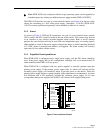
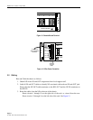
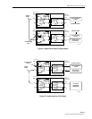
7. Attach power wires, –48V and return. A second set of terminals (-48V (2) and RET (2))
is provided if a backup power source is desired. See Figure 14.
8. Attach wires from pre-existing alarm system (if any) to the alarm contacts on the power
supply unit.
Note:
Use only the PS1 alarms if the chassis is configured with one power supply. Use
PS1 and PS2 alarms if the chassis is configured with dual (redundant) power supplies.
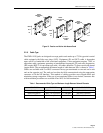
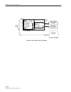
TEST
16
15
14
13
12
11
10
9
8
7
6
5
4
3
2
1
AVIS-16
SIGNAL OUTPUT
SIGNAL INPUT
CHASSIS GROUND
12251-B
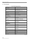
1
1
1
2
2
3
4
CABLE
MANAGEMENT
TRAY
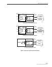
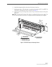
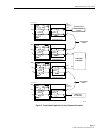
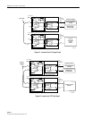
2 MOUNTING BRACKET–
23-INCH RACK FLUSH
MOUNTING SHOWN
MOUNTING BRACKET
RECESS POSITIONS
1. 23-INCH RACK FLUSH
2. 19-INCH RACK FLUSH
3. 23-INCH RACK 2-INCH RECESS
4. 19-INCH RACK 2-INCH RECESS
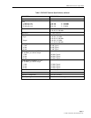
SPARE
SPARE
–48V (1)
RET (1)
–48V (2)
RET (2)
PS1 ALM A
PS1 ALM B
PS2 ALM A
PS2 ALM B
CLASS 2
Figure 12. PWR-AVIS Chassis with Mounting Positions