


10
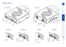
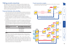
Making standard connections
Connections to the AdderLink AV modules do not need to follow the precise
order given in this user guide although it is recommended that you do not apply
power to the modules until all other connections have been made.
Note: Unless stated otherwise, all connection information given here applies to
all modules in the AdderLink AV family.
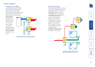
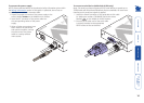
Connections at the transmitter
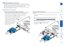
To connect video and audio from the source PC system
1 Attach a video cable of suitable type and length (fully shielded with 15 way
male D-type connectors at both ends, 2m or less - Adder part number:
VSC18) to the socket labelled
IN
on the AdderLink AV transmitter.
2 Attach the other end of the video cable to the appropriate VGA
video output socket on the source PC system.
3 Attach a stereo audio cable (shielded with three way
3.5mm jack plugs at both ends - Adder part
number: VSC22) to the socket labelled
IN
on
the AdderLink AV transmitter.
4 Attach the other end of the stereo
audio cable to the appropriate
audio output socket on the
source PC system.
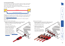
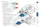
To connect a monitor and speakers
The video and audio out ports of the AdderLink AV transmitter can optionally be
used either to:
• Attach a monitor and/or speakers in the vicinity of the source PC system
– See below,
or
• Make a cascade link to another transmitter module – Please refer to the
section Making cascade connections – Cascading transmitters.
1 Attach the video cable from the monitor to the socket labelled
OUT
on the AdderLink AV transmitter.
2 Attach the stereo audio cable from the speakers to
the socket labelled
OUT
on the AdderLink AV
transmitter.
TRANSMITTER
LINK
2
LINK
3
LINK
4
104
ADDERLINK
IN
IN
TRANSMITTER
LINK
2
LINK
3
LINK
4
10
4
ADDERLINK
IN
IN