


15
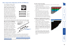
Making cascade connections
The AdderLink AV series of products have been specically designed to be
exible in order to support both your immediate and future needs for media
streaming. In addition to the standard connections made from transmitters to
receivers, you can also link extra transmitters to transmitters and/or receivers to
receivers in order to provide more display/speaker outputs. These non-standard
links are called cascade connections.
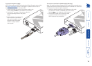
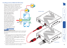
Important limitations when cascading
• There should never be more than three cascade connections between the
primary transmitter (the one connected to the source PC) and any receiver.
The cascade connections can all occur at the transmitter end or all at the
receiver end (AV101 modules only) or at a mixture of both.
• The RS232 serial port of an AdderLink AV200 transmitter cannot be
cascaded, therefore, if an AV200 transmitter is involved in a cascade, it
should be placed as the primary transmitter, connected directly to the source
PC system.
• Each cascade connection reduces the overall link length permissible from a
transmitter to the nal receiver in a branch. To calculate the recommended
overall maximum link length for a branch, count the number of cascade
connections between the primary transmitter and the nal receiver in that
branch. The effects of cascade connections on overall branch link lengths are
as follows:
Number of cascade connections Overall length of links for a branch
(in a branch) (from transmitter to furthest receiver)
0 300m (1000 feet)
1 250m (800 feet)
2 200m (650 feet)
3 175m (600 feet)
Notes
The lengths of transmitter cascade (video) connections should never be
longer than 2m (6 feet) and can be considered to have a negligible effect
upon overall link lengths.
The maximum resolutions achievable are: 1600 x 1200 x 60Hz at 200m
and 1280 x 1024 x 60Hz at 300m. If you are using lower resolutions then it
may be possible to achieve longer transmission distances than shown in the
above table although we do not recommend runs longer than 300m in any
installation. If you are running shorter cables then it may be possible to use
more cascades than shown in the above table.
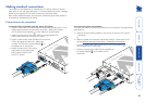
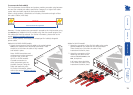
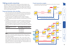
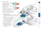
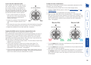
Cascade connection examples
These examples demonstrate valid congurations and the effect of cascade
connections upon overall link lengths:
RECEIVER
RECEIVER
RECEIVER
TRANSMITTER
Overall maximum length for link with no cascades: 300m
Overall maximum length for link with 1 cascade: 250m
Cascade 1
Branch 1
Branch
2
STANDARD LINK
STANDARD LINK
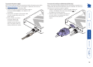
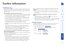
RECEIVER
RECEIVER
RECEIVER
RECEIVER
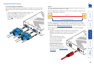
RECEIVER
RECEIVER
RECEIVER
RECEIVER
RECEIVER
Primary
Transmitter
TRANSMITTER
TRANSMITTER
TRANSMITTER
Cascade 1
Cascade 2
Cascade
2
Cascade 3
Cascade 3
From PC
Branch
1
Branch
2
Branch
3
Overall maximum length for link with 3 cascades: 175m
Cascade 1
Cascade 3
Cascade 2
STANDARD LINK
STANDARD LINK
STANDARD LINK