


11
To connect the link cable(s)
The links between the transmitter and receiver modules are made using between
one and four twisted pair cables, specied to Category 5 or higher. Each cable
carries video and audio signals to each receiver module.
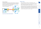
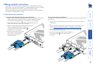
When a single receiver is attached to a link cable, the maximum length of that
link cable is 300m (1000 feet).
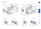
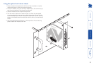
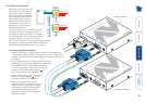
AdderLink AV104 models
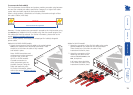
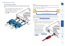
1 Attach the connector of the rst link cable to the socket
labelled L1 OUT on the AdderLink AV104 transmitter.
There should be a click when the cable is fully
inserted and locked in place.
2 Attach the connectors of the
remaining link cables to the
sockets labelled L2 OUT to L4
OUT, as required.
In all cases, there should be
a click when the cable is fully
inserted and locked in place.
TRANSMITTER
ADDERLINK
IN
IN
10
0
TRANSMITTER
LINK
2
LINK
3
LINK
4
104
ADDERLINK
IN
IN
RECEIVERTRANSMITTER
Overall maximum link length: 300m
STANDARD LINK
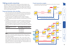
However, if further receivers are connected in cascade to the initial receiver using
its LINK OUT port (AdderLink AV101 models only), then the overall length of the
link cables used must be reduced. For further information, please refer to the
section Making cascade connections.
NOTE: Where possible, avoid laying the twisted pair link cable(s) alongside
power cables.
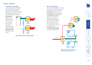
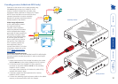
AdderLink AV100 & AV200 models
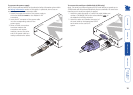
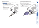
1 Attach the connector of the link cable to the socket labelled
LINK on the AdderLink AV100/AV200 transmitter. There
should be a click when the cable is fully inserted
and locked in place.
Note: AV200 transmitters and
receivers must not be connected,
via a CATx link, to AV100,
AV101 or AV104 modules.
Cascade connections to
other transmitter types are
possible, however, using the
video and audio out ports.
For further information, please
refer to the section Making cascade
connections.