


19
Skew compensation adjustments (AV101 & AV200 only)
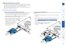
The twisted pair cabling used to
link the AdderLink AV modules
consists of four pairs of wires per
cable. Three of these pairs are
used to convey the red, green and
blue video signals. Due to slight
differences in twist rate between
the wire pairs, the red, green and
blue video signals may not arrive
at precisely the same time. This
effect is visible as separate colour
shadows on high contrast images
and is particularly apparent when
using higher screen resolutions over
long distances and also when using
certain types of category 5e cables.
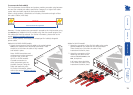
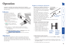
Skew compensation adjustments are made using two rotary dials, the rst
affects the relationship between the green and blue colour signals (SKEW
GB) while the second (SKEW RG)
operates similarly on the red and
green signals. Each dial delays one
of its stated colours in relation
to the other. By using both dials
it is possible to correctly align all
three colours. The effects of skew
are easiest to view and adjust
when distinct red, green and blue
elements, in close proximity, are
present within the screen image. An
appropriate test pattern is supplied
on the AdderLink AV CD-ROM or
alternatively you can create your own test pattern as discussed opposite.
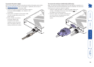
NOTE: Skew adjustment is available on the AV101 receiver at any time.
However, the AV200 must be placed into skew adjustment mode as power is
applied. Please refer to the section To place the AV200 receiver into skew
compensation mode.
NOTE: Both video outputs are equally affected by your skew adjustments.
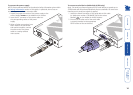
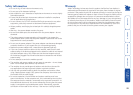
SKEW
GB
SKEW
RG
BRIGHT
SHARP
ADDERLINK
SKEW RG dial
SKEW GB dial
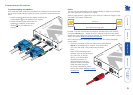
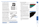
To create a skew test pattern
1 Run any image creation/editing application, such as the Paint program
supplied with Windows.
2 Using the image application create three
stacked horizontal rectangles (one red, one
green and one blue) that ll the width of
the screen.
3 Draw a vertical black line down across
the coloured bars and then repeat this
vertical line at intervals along the width
of the coloured bars. These lines create
breaks across the colours and give you
more opportunities to view the horizontal
position of each colour relative to the others.
To display the supplied skew test pattern
1 Insert the supplied Adder CD-ROM into the
CD player of the computer.
2 Within Windows, use the My Computer
option (usually available as a desktop icon
or within the Start menu) to view the
contents of the CD-ROM. Double-click the
SkewTest entry to display the standard test
pattern. If necessary, select the Full screen
option from the File menu to maximise the
application window so that the image lls
the screen.
The screen will show a series of ne red,
green and blue crosses which should all
be in line, vertically and horizontally- skew
affects the horizontal placement of the
colours.
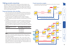
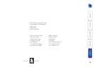
1 2 3 4 5 6 7 8
8
6
5
2
8
6
5
2
Data signal
Red
video signal
Green
video signal
Blue
video signal
7
3
4
1
7
3
4
1