


17
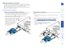
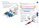
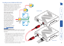
Cascading receivers (AdderLink AV101 only)
Expansion at the receiver end is made possible using
the LINK OUT ports present on AdderLink AV101
receivers. Receiver cascade links are made using
twisted pair cables, specied to Category 5 or higher.
NOTE: Ensure that there are no more than three
cascades (transmitter or receiver cascades)
between the primary transmitter and the
furthest receiver in any branch.
RECEIVER
101
STANDARD
LINK
CASCADE LINK
CASCADE LINK
POWER
RECEIVER
RECEIVER
101
101
Primary
Receiver
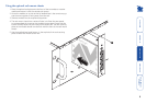
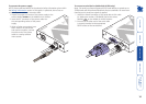
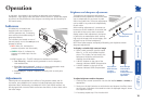
Video image adjustments
As link cable lengths increase
and more receivers are
cascaded, colour separation
effects may become noticeable
within displayed video images,
particularly at higher resolutions.
These effects are called ‘skew’
and result from differing delays
on the red, green and blue
colour signals as they travel to
the receivers. Each AdderLink
AV101 receiver provides two
extra adjustment dials to
counter skew effects. For further
information, please refer to the
section Skew compensation
adjustments.
RECEIVER
SKEW
GB
SKEW
RG
BRIGHT
SHARP
LINKOU
T
101
ADDERLINK
OUT
OUT
RECEIVER
SKEW
GB
SKEW
RG
BRIGHT
SHARP
LINK
OU
T
101
ADDERLINK
OUT
OUT
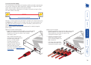
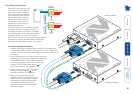
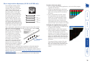
To connect cascaded receivers
NOTE: Please observe the recommended overall link cable lengths
(including receiver cascade connections) in order to avoid signal
degradation.
1 Attach the connector of the cascade link cable to the socket
labelled LINK OUT on the primary AdderLink AV101 receiver.
2 At the other end of the cascade link cable, attach the
connector to the socket labelled LINK IN on the secondary
AdderLink AV101 receiver.
In all cases, there should be a click when the cable is fully
inserted and locked in place.
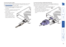
3 If necessary, repeat the above procedure for a tertiary
AdderLink AV101 receiver.
4 Connect the remaining signal and power cables to the added
receivers, as discussed earlier within this chapter.
Primary receiver
Secondary receiver