


Installation
15
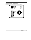
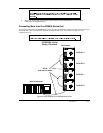
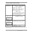
The SCSI ID switch is located on the rear of the DS9000 Series (see Figure 7). Use a small pointed object to press
either the + button on the bottom, or the minus button on the top of the switch to select the proper ID.
Count each device's SCSI IDs in order from 0 to 7 (or from 0 to 15) on each SCSI bus to confirm that no
two devices have the same ID number assigned.
Note
Check the SCSI Bus Termination
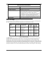
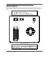
SCSI buses require termination at each end for proper operation. A typical external subsystem installation would be
terminated at the SCSI host adapter and at the last device in the chain.
If an external device is being used with an internal device (on the same channel), the SCSI host adapter would now
be in the middle of the bus rather than at the end. In this case, the termination would be at the internal device and the
last drive in the external chain. The terminators on the SCSI host adapter would be removed. Refer to the SCSI host
adapter manual for directions on removing the terminators on the board.
Is there a terminator installed on each end of the SCSI bus?
Note
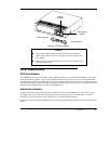
Connecting Power and Turning On
Plug the power cord into the back of the DS9000 Series.
Plug the power cord from the DS9000 Series into a GROUNDED electrical outlet.
Plug the power cord from the host system into the same GROUNDED electrical circuit if
possible. Computers and peripherals should always share the same grounds.
Turn
ON
the power to the host system.
Turn the DS9000 Series power
ON
.