13
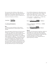
The convention for definition of offset delay in
waveguide requires entry of the delay assuming no
dispersion. For waveguide transmission line, the
Agilent 8510 calculates the effects of dispersion as
a function of frequency as follows:
f
co
= lower cutoff frequency
f = measurement frequency
Note
To assure accurate definition of offset delay, a
physical measurement of offset length is recom-
mended.
The actual length of offset shorts will vary by man-
ufacturer. For example, the physical length of a
1
/8 λ offset depends on the center frequency chosen.
In waveguide this may correspond to the arith-
metic or geometric mean frequency. The arithmetic
mean frequency is simply (F
1
+ F
2
)/2, where F
1
and
F
2
are minimum and maximum operating frequen-
cies of the waveguide type. The geometric mean
frequency is calculated as the square root of F
1
x
F
2
. The corresponding (λg) is then calculated from
the mean frequency and the cutoff frequency of the
waveguide type. Fractional wavelength offsets are
then specified with respect to this wavelength.
For the WR-62 calibration kit, offset delay is zero
for the “thru” (std #4) and the “load” (std #3). To
find the offset delay of the
1
/8 λ and
3
/8 λ offset
shorts, precise offset length measurements are nec-
essary. For the
1
/
8
λ offset short, l = 3.24605 mm,
ε
r
= 1.000649, c = 2.997925 x 10
8
m/s.
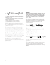
Delay =
(3.24605 x 10
-3
m) (√1.000649)
= 10.8309 pS
2.997925 x 10
8
m/s
For the
3
/8 λ offset short, I = 9.7377 mm, ε
r
= 1.000649,
c = 2.997925 x 10
8
m/s.
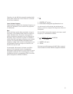
Delay =
(9.7377 x 10
-3
m) (√1.000649)
= 32.4925 pS
2.997925 x 10
8
m/s
Offset Z
0
Offset Z
0
is the characteristic impedance within the
offset length. For coaxial type offset standards,
specify the real (resistive) part of the characteris-
tic impedance in the transmission media. The char-
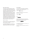
acteristic impedance in lossless coaxial
transmission media can be calculated from its
physical geometry as follows.
Actual delay =
Linear delay
1 - (fco/f)
2


