


20
Each adapter is specified as a single delay/thru
standard and up to seven standards numbers can
be specified into the adapter class.
Standard Class labels
Standard Class labels are entered to facilitate
menu-driven calibration. A label can be any user-
selected term which best describes the device or
class of devices that the operator should connect.
Predefined labels exist for each class. These labels
are
S
11
A, S
11
B, S
11
C, S
22
A, S
22
B, S
22
C, FWD TRANS,
FWD MATCH, REV TRANS, REV MATCH,
RESPONSE, FWD ISOLATION, REV ISOLATION,
THRU, REFLECT, LINE, and ADAPTER.
The class labels for the WR-62 waveguide calibra-
tion kit are as follows; S
11
A and S
22
A–PSHORT1;
S
11
B and S
22
B–PSHORT2; S
11
C and S
22
C–PLOAD;
FWD TRANS, FWD MATCH, REV TRANS and REV
MATCH–PTHRU; and RESPONSE–RESPONSE.
TRL options
When performing a TRL 2-PORT calibration, cer-
tain options may be selected. CAL Z is used to
specify whether skin-effect-related impedance vari-
ation is to be used or not. Skin effect in lossy
transmission line standards will cause a frequency-
dependent variation in impedance. This variation
can be compensated when the skin loss (offset
loss) and the mechanically derived impedance
(Offset Z
0
) are specified and CAL Z
0
: SYSTEM Z
0
selected. CAL Z
0
: LINE Z
0
specifies that the imped-
ance of the line is equal to the Offset Z
0
at all
frequencies.
The phase reference can be specified by the Thru
or Reflect during the TRL 2-PORT calibration. SET
REF: THRU corresponds to a reference plane set by
Thru standard (or the ratio of the physical lengths
of the Thru and Line) and SET REF: REFLECT cor-
responds to the Reflect standard.
LOWBAND FREQUENCY is used to select the mini-
mum frequency for coaxial TRL calibrations. Below
this frequency (typically 2 to 3 GHz) full 2-port
calibrations are used.
Note
The resultant calibration is a single cal set
combining the TRL and conventional full 2-port
calibrations. For best results, use TRM calibration
to cover frequencies below TRL cut-off frequency.
Calibration kit label
A calibration kit label is selected to describe the
connector type of the devices to be measured. If a
new label is not generated, the calibration kit label
for the kit previously contained in that calibration
kit register (CAL 1 or CAL 2) will remain. The pre-
defined labels for the two calibration kit registers
are:
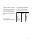
Calibration kit 1 Cal 1 Agilent 85050B
7-mm B.1
Calibration kit 2 Cal 2 Agilent 85052B
3.5-mm B.1