


7
Modification procedure
Calibration kit modification provides the capability
to adapt to measurement calibrations in other con-
nector types or to generate more precise error
models from existing kits. Provided the appropri-
ate standards are available, cal kit modification
can be used to establish a reference plane in the
same transmission media as the test devices and at
a specified point, generally the point of device con-
nection/insertion. After calibration, the resultant
measurement system, including any adapters
which would reduce system directivity, is fully cor-
rected and the systematic measurement errors are
mathematically removed. Additionally, the modifi-
cation function allows the user to input more pre-
cise physical definitions for the standards in a
given cal kit. The process to modify or create a cal
kit consists of the following steps:
1. Select standards
2. Define standards
3. Assign classes
4. Enter standards/classes
5. Verify performance
To further illustrate, an example waveguide cali-
bration kit is developed as the general descriptions
in MODIFY CAL KIT process are presented.
Select standards
Determine what standards are necessary for cali-
bration and are available in the transmission
media of the test devices.
Calibration standards are chosen based on the fol-
lowing criteria:
• A well defined response which is mechanically
repeatable and stable over typical ambient tem-
peratures and conditions. The most common
coaxial standards are zero-electrical-length
short, shielded open and matched load termina-
tions which ideally have fixed magnitude and
broadband phase response. Since waveguide
open circuits are generally not modelable, the
types of standards typically used for waveguide
calibration are a pair of offset shorts and a fixed
or sliding load.
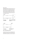
• A unique and distinct frequency response. To
fully calibrate each test port (that is to provide
the standards necessary for S
11
or S
22
1-PORT
calibration), three standards are required that
exhibit distinct phase and/or magnitude at each
particular frequency within the calibration
band. For example, in coax, a zero-length short
and a perfect shielded open exhibit 180 degree
phase separation while a matched load will pro-
vide 40 to 50 dB magnitude separation from
both the short and the open. In waveguide, a
pair of offset shorts of correct length provide
phase separation.
• Broadband frequency coverage. In broadband
applications, it is often difficult to find stan-
dards that exhibit a known, suitable response
over the entire band. A set of frequency-banded
standards of the same type can be selected in
order to characterize the full measurement
band.
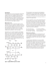
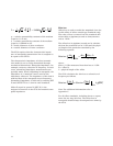
• The TRL 2-PORT calibration requires only a sin-
gle precision impedance standard—a transmis-
sion line. An unknown high reflection device
and a thru connection are sufficient to complete
this technique.