


3
Introduction
This product note covers measurement calibration
requirements for the Agilent 8510B/C network
analyzer. All of the capabilities described in this
note also apply to the Agilent 8510A with the
following exceptions: response & isolation calibra-
tion; short circuit inductance; class assignments
for forward/reverse isolation, TRL thru, reflect,
line and options; and adapter removal.
Measurement errors
Measurement errors in network analysis can be
separated into two categories: random and system-
atic errors. Both random and systematic errors are
vector quantities. Random errors are non-repeat-
able measurement variations and are usually
unpredictable. Systematic errors are repeatable
measurement variations in the test setup.
Systematic errors include mismatch and leakage
signals in the test setup, isolation characteristics
between the reference and test signal paths, and
system frequency response. In most microwave
measurements, systematic errors are the most sig-
nificant source of measurement uncertainty. The
source of these errors can be attributed to the sig-
nal separation scheme used.
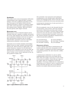
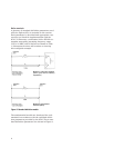
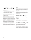
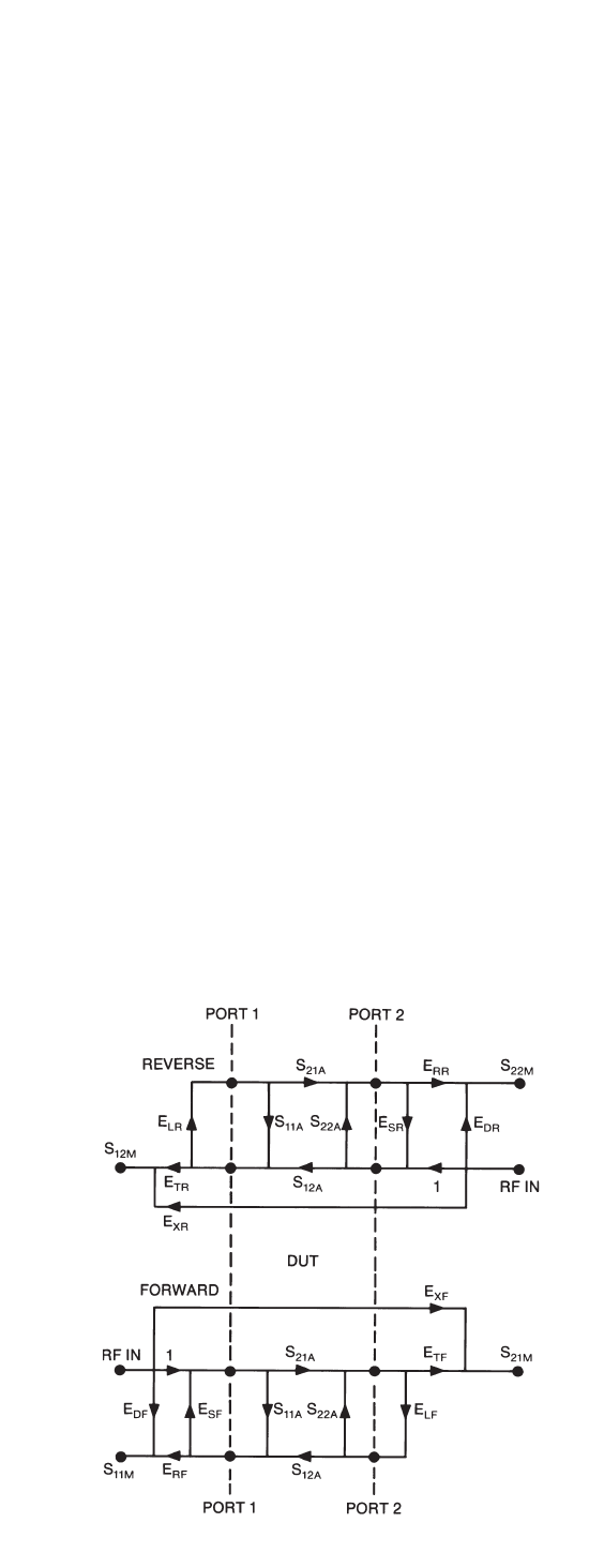
The systematic errors present in an S-parameter
measurement can be modeled with a signal flow-
graph. The flowgraph model, which is used for error
correction in the 8510 for the errors associated with
measuring the S-parameters of a two port device, is
shown in the figure below.
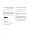
The six systematic errors in the forward direction
are directivity, source match, reflection tracking,
load match, transmission tracking, and isolation.
The reverse error model is a mirror image, giving a
total of 12 errors for two-port measurements. The
process of removing these systematic errors from
the network analyzer S-parameter measurement is
called measurement calibration.
E
DF
, E
DR
-Directivity E
LF
, E
LR
-Load Match
E
SF
, E
SR
-Source Match E
TF
, E
TR
-Trans. Tracking
E
RF
, E
RR
-Refl. Tracking E
XF
, E
XR
-Isolation
Measurement calibration
A more complete definition of measurement cali-
bration using the 8510, and a description of the
error models is included in the 8510 operating and
programming manual. The basic ideas are summa-
rized here.
A measurement calibration is a process which
mathematically derives the error model for the
8510. This error model is an array of vector coeffi-
cients used to establish a fixed reference plane of
zero phase shift, zero magnitude and known
impedance. The array coefficients are computed by
measuring a set of “known” devices connected at a
fixed point and solving as the vector difference
between the modeled and measured response.
Figure 1. Agilent 8510 full 2-port error model