


24
Front panel procedure: (P-band waveguide example)
1. Prior to modifying or generating a cal kit, store
one or both of the cal kits in the 8510’s non-
volatile memory to a disk.
2. Select CAL menu, MORE.
3. Prepare to modify cal kit 2: press MODIFY 2.
4. To define a standard: press DEFINE STANDARD.
5. Enable standard no. 1 to be modified: press 1,
X1.
6. Select standard type: SHORT.
7. Specify an offset: SPECIFY OFFSETS.
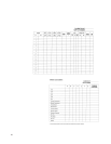
8. Enter the delay from Table 1: OFFSET DELAY,
0.0108309, ns.
9. Enter the loss from Table 1: OFFSET LOSS, 0,
X1.
10. Enter the Z
0
from Table 1: OFFSET Z
0
, 50, X1.
11. Enter the lower cutoff frequency: MINIMUM
FREQUENCY, 9.487 GHz.
12. Enter the upper frequency: MAXIMUM FRE-
QUENCY, 18.97 GHz.
13. Select WAVEGUIDE.
14. Prepare to label the new standard: PRIOR
MENU, LABEL STANDARD, ERASE TITLE.
15. Enter PSHORT 1 by using the knob, SELECT
LETTER soft key and SPACE soft key.
16. Complete the title entry by pressing TITLE
DONE.
17. Complete the standard modification by press-
ing STANDARD DONE (DEFINED).
Standard #1 has now been defined for a
1
/8 λ P-band
waveguide offset short. To define the remaining
standards, refer to Table 1 and repeat steps 4 -17.
To define standard #3, a matched load, specify
“fixed.”
The front panel procedure to implement the class
assignments of Table 2 for the P-band waveguide
cal kit are as follows:
1. Prepare to specify a class: SPECIFY CLASS.
2. Select standard class S
11
A.
3. Inform the 8510 to use standard no. 1 for the
S
11
A class of calibration: l, X1, CLASS DONE
(SPECIFIED).