


22
User modified cal kits and Agilent 8510
specifications
As noted previously, the resultant accuracy of the
8510 when used with any calibration kit is depend-
ent on how well its standards are defined and is
verified through measurement of a device with
traceable frequency response.
The published Measurement Specifications for the
8510 Network Analyzer system include calibration
with Agilent calibration kits such as the 85050B.
Measurement calibrations made with user defined
or modified calibration kits are not subject to the
8510 performance specifications although a proce-
dure similar to the standard verification procedure
may be used.
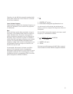
Modification examples
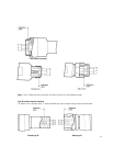
Modeling a “thru” adapter
The MODIFY CAL KIT function allows more precise
definition of existing standards, such as the “thru.”
For example, when measuring devices with the
same sex coaxial connectors, a set of “thru” stan-
dards to adapt non-insertable devices on each end
is needed. Various techniques are used to cancel
the effects of the “thru” adapters. However, using
the modify cal kit function to make a precise defi-
nition of the “thru” enables the 8510 to mathemati-
cally “remove” the attenuation and phase shift due
to the “thru” adapter. To model correctly a “thru”
of fixed length, accurate gauging (see OFFSET
DELAY) and a precise measurement of skin-loss
attenuation (see OFFSET LOSS) are required. The
characteristic impedance of the “thru” can be
found from the inner and outer conductor diame-
ters and the permittivity of the dielectric (see OFF-
SET Z
0
).
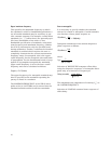
Modeling an arbitrary impedance standard
The arbitrary impedance standard allows the user
to model the actual response of any one port pas-
sive device for use as a calibration standard. As
previously stated, the calibration is mathematically
derived by comparing the measured response to
the known response which is modeled through the
standard definition table. However, when the
known response of a one-port standard is not
purely reflective (short/open) or perfectly matched
(load) but the response has a fixed real impedance,
then it can be modeled as an arbitrary impedance.
A “load” type standard has an assigned terminal
impedance equal to the system Z
0
. If a given load
has an impedance which is other than the system
Z
0
, the load itself will produce a systematic error in
solving for the directivity of the measurement sys-
tem during calibration. A portion of the incident
signal will be reflected from the mismatched load
and sum together with the actual leakage between
the reference and test channels within the meas-
urement system. However, since this reflection is
systematic and predictable (provided the terminat-
ing impedance is known) it may be mathematically
removed. The calibration can be improved if the
standard’s terminal impedance is entered into the
definition table as an arbitrary impedance rather
than as a “load.”
A procedure similar to that used for measurement
of open circuit capacitance (see method #3) could
be used to make a calibrated measurement of the
terminal impedance.