


System-Board Assembly 95
19
System-Board Assembly
WARNING: Before working inside your computer, read the safety information
that shipped with your computer and follow the steps in "Before You Begin" on
page 13. For additional safety best practices information, see the Regulatory
Compliance Homepage at dell.com/regulatory_compliance.
Prerequisites
1
Remove the left side-panel. See "Removing the Left Side-Panel" on
page 25.
1
Remove the memory fan. See "Removing the Memory Fan" on page 67.
2
Open the PCI shroud. See "Opening the PCI Shroud" on page 45.
3
Remove the graphics card. See "Removing the Graphics Card" on page 57.
4
Remove the PCI-Express x1 card. See "Removing the PCI-Express x1
Card" on page 49.
5
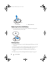
Remove the coin-cell battery. See "Removing the Coin-Cell Battery" on
page 89.
6
Remove the memory module(s). See "Memory Module(s)" on page 63.
7
Remove the processor liquid-cooling assembly. See "Removing the
Processor Liquid-Cooling Assembly" on page 71.
8
Remove the processor. See "Removing the Processor" on page 75.
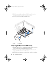
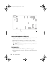
Removing the System-Board Assembly
NOTE: Your computer’s service tag is stored in the system board. You must enter
the service tag in the BIOS after you replace the system-board assembly.
NOTE: Before disconnecting the cables from the system board, note the location of
the connectors, so that you can reconnect them correctly after you replace the
system-board assembly.
1
Disconnect all the cables connected to the system-board assembly.
2
Remove the screws that secure the system-board assembly to the chassis.
book.book Page 95 Wednesday, May 16, 2012 2:37 PM