


IX5-28GPX Installation Guide
17
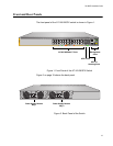
Note
SFP and SFP+ transceivers must be purchased separately. For a
list of supported transceivers, contact your Allied Telesis distributor
or reseller.
Note
SFP+ slots 27 and 28 are initially configured as stacking slots for the
VCStack feature. If you intend to use the switch as a stand-alone
unit, you must disable the VCStack feature before using the slots
with standard SFP or SFP+ transceivers. See Chapter 5,
“Configuring the Switch for Stand-alone Operations” on page 77 for
instructions.
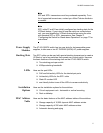
Power Supply
Modules
The AT-IX5-28GPX switch has two rear slots for hot-swappable power
supplies, to take one or two AT-PWR800 (800W) AC power supplies.
Stacking Slots Two SFP+ slots can be used with special stacking transceivers to create a
VCStack of up to four switches that operate as a virtual switch. Here are
the basic features of the stacking slots on the AT-IX5-28GPX switch:
Two stacking ports per switch
40Gbps stacking bandwidth
LEDs Here are the port LEDs:
PoE and link/activity LEDs for the twisted pair ports
Link/activity LEDs for the SFP+ slots
Stack ID number LED
eco-friendly button turns off the LEDs to conserve electricity
Installation
Options
Here are the installation options for the switches:
19-inch equipment rack - horizontal or vertical mounting
Desk or tabletop
MAC Address
Table
Here are the basic features of the MAC address tables of the switches:
Storage capacity of 16,000 dynamic MAC address entries
Storage capacity of 256 static MAC address entries
Automatic learning and aging