


x510 Series Installation Guide for Virtual Chassis Stacking
57
Planning a Stack
Here are the guidelines to planning a stack:
A stack can have up to four AT-IX5-28GPX switches.
Any of the switches in the stack can be the master switch.
Switches connected with AT-StackXS/1.0 stacking cables should
be installed in a standard 19-inch equipment rack and not more
than one meter apart, the length of the stacking cable. The end
switches cannot be more than one meter apart if you want to
create the ring topology, shown in Figure 13 on page 46 and Figure
14 on page 47.
You may use the AT-StackOP/0.3 and AT-StackOP/9.0
transceivers to build stacks of switches that are up to 300 meters
and 9 kilometers apart, respectively.
The wiring topology of the stack may be either linear or ring. Both
topologies offer the same in terms of speed, but the ring topology
adds wiring redundancy.
You can use combinations of AT-StackXS/1.0, AT-StackOP/0.3,
and AT-StackOP/9.0 cables when the individual switches of the
stack are at various distances from each other.
The switches do not need any additional software for stacking.
However, they do need stacking transceivers.
You may not install a networking device, such as a media
converter or Ethernet switch, between two fiber optic stacking
transceivers.
All switches must have the same licenses of optional features. If
you install an optional feature on one switch, you must install it on
all switches before assembling the stack.
The AT-StackOP/9.0 transceiver has a maximum operating
distance of 9 kilometers and requires 9/125 µm single-mode fiber
optic cable. The operating specifications of the transceiver are
listed in Table 17 on page 129.
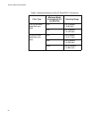
Table 8 on page 58 lists the maximum distances of the AT-
StackOP/0.3 transceiver. The operating specifications of the
transceiver are listed in Table 16 on page 128.