


Chapter 4: Installing the Switch and its Power Supplies
64
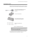
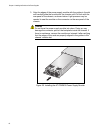
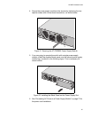
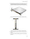
3. Align the edges of the power supply module with the guides in the slot
and carefully slide the module into the chassis until it is flush with the
rear panel of the chassis, as shown below. Light pressure may be
needed to seat the module on the connector on the rear panel of the
chassis.
Caution
Do not force the power supply module into place. Doing so may
damage the connector pins on the backplane inside the chassis. If
there is resistance, remove the module and reinsert it after verifying
that the edges of the card are properly aligned in the guides in the
chassis’ module slot.
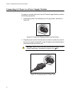
Figure 20. Installing the AT-PWR800 Power Supply Module
2261
100
-240VAC~ 12A MAX
D
C PWR
F
A
UL
T
AT-PWR8000