


Chapter 1: Overview
32
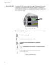
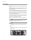
LEDs for the
SFP+ Slots
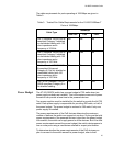
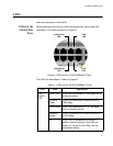
The LEDs for the SFP+ slots are located between the slots, as shown in
Figure 5. Each SFP+ slot has one LED. The left-hand LED is for the top
slot and the right-hand LED is for the bottom slot.
Figure 5. SFP+ Slot LEDs
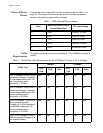
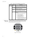
PoE Green The switch is detecting a powered device
(PD) on the port and is delivering power to it
Solid Amber The switch has shutdown PoE+ on the port
because of a fault condition.
Flashing
Amber
The switch is detecting a PD on the port but
is not delivering power to it because the
maximum power budget has been reached.
Off This LED state can result from the following
conditions:
The port is not connected to a PD.
The PD is powered off.
The port is disabled in the
management software.
PoE is disabled on the port.
The LEDs on the Ethernet line cards
are turned off. To turn on the LEDs,
use the eco-friendly button.
Table 4. LEDs on the 10/100/1000Base-T Ports (Continued)
LED State Description
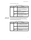
SFP+ Slot LEDs