


IX5-28GPX Installation Guide
33
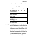
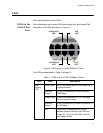
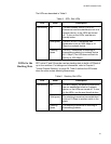
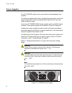
The LEDs are described in Table 5.
LEDs for the
Stacking Slots
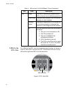
SFP+ slots 27 and 28 may be used as stacking slots to build a VCStack of
up to four switches. For background information, refer to Chapter 2,
“Virtual Chassis Stacking” on page 39. Table 6 defines the LED states
when the slots contain stacking transceivers.
Table 5. SFP+ Slot LEDs
LED State Description
Link/Activity Off The slot is empty, the SFP or SFP+
transceiver has not established a link to a
network device, or the LEDs are turned
off. To turn on the LEDs, use the eco-
friendly button.
Solid green The SFP or SFP+ transceiver has
established a link at 1000 Mbps or 10
Gbps to a network device.
Flashing
green
The SFP+ transceiver is receiving or
transmitting packets to a network device
at 10 Gbps. (The LED does not flash for
activity at 1000 Mbps.).
Table 6. Stacking Slot LEDs
LED State Description
Link/Activity Off The slot is empty, the stacking transceiver
has not established a link to a network
device, or the LEDs are turned off. To turn
on the LEDs, use the eco-friendly button.
Solid green The stacking transceiver has established
a link at 10 Gbps to another switch in the
stack.
Flashing
green
The stacking transceiver is receiving or
transmitting packets.