


IX5-28GPX Installation Guide
19
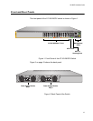
Front and Rear Panels
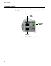
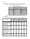
The front panel of the AT-IX5-28GPX switch is shown in Figure 1.
Figure 1. Front Panel of the AT-IX5-28GPX Switch
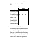
Figure 2 on page 19 shows the back panel.
Figure 2. Back Panel of the Switch
10/100/1000Base-T Ports
SFP+ Slots
Management
Panel
SFP+ or
Stacking Slots
S2/28
S1/27
26
25
CONSOLE
2661
IX5-28GPX
FDX HDX COL
1000 LINK ACT 10/100 LINK ACT
SFP+
Power Supply Module
Bay 1
2001
100-240VAC~ 5A MAX
DC PWR
FAULT
AT-PWR800
100-240VAC~ 5A MAX
DC PWR
FAULT
AT-PWR800
Power Supply Module
Bay 2