


IX5-28GPX Installation Guide
67
Installing the Switch in an Equipment Rack
This procedure requires the following items:
Twelve bracket screws (included with the switch)
Two equipment rack brackets (included with the switch)
Flat-head screwdriver (not provided)
Cross-head screwdriver (not provided)
Four standard equipment rack screws (not provided)
Installation guidelines may be found in “Choosing a Site for the Switches”
on page 56. Here is the procedure for installing the switch horizontally or
vertically in a 19-inch equipment rack.
Caution
The chassis may be heavy and awkward to lift. Allied Telesis
recommends that you get assistance when mounting the chassis in
an equipment rack. E28
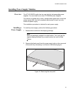
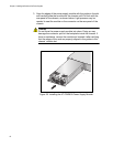
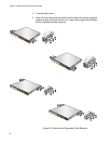
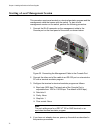
1. Place the unit upside down on a level, secure surface.
Figure 23. Turning the Switch Upside Down
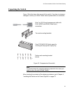
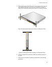
2. Using a flat-head screwdriver, pry the rubber feet from the bottom of
the switch, as shown in Figure 24.
Figure 24. Removing the Rubber Feet
2668
S2/28
S1/27
26
25
CONSOLE
IX5-28GPX
FDX HDX COL
1000 LINK ACT 10/100 LINK ACT
SFP+
IX5-28GPX
1
2
2669