


Installation
33
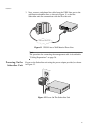
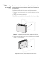
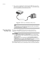
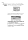
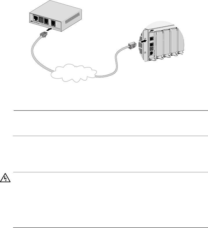
3. Next, connect a telephone line cable from the VDSL Line port to the
wall/interior telephone line, as shown in Figure 22, so that the Provider
unit can communicate with the Subscriber unit.
Figure 22 VDSL Line to Wall/Interior Phone Line
Note
The procedure for connecting the management cable is described in
”Cabling Preparations” on page 36.
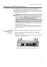
Powering On the
Provider Unit
Powering on the AT-MC602 Provider Unit requires that the host
equipment, AT-MCR12 rackmount chassis, is powered on as well.
Warning
The QUALIFIED SERVICE PERSONNEL must verify that the
AT-MCR12 power cord is connected to the socket provided with the
ground conductor.
If the power cord is not connected, the QUALIFIED SERVICE
PERSONNEL must install a permanent ground connection using the
bond stud on the rear panel of the AT-MCR12 chassis.
For detailed information on how to power on the AT-MCR12 unit, refer to
the AT-MCR12 Media Converter Rackmount Chassis Installation Manual.
M
C
R
1
2
LINE
10BaseT /
100BaseTX
LINK
ACT
PWR
ERR
LINK
MGMT
AT-MC602
VDSL EXTENDED ETHERNET
PSTN
L
I
N
E
1
0
B
a
s
e
T
/
1
0
0
B
a
s
e
T
X
P
S
T
N
L
I
N
K
A
C
T
P
W
R
E
R
R
L
I
N
K
M
G
M
T
AT-MC601
V
D
S
L
E
X
T
E
N
D
E
D
E
T
H
E
R
N
E
T
Wall/Interior Phone Line