


MULTITASKER™
400-0132-005
11
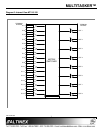
Example:
If Input 1 is connected to all outputs, but only 1
through 4 are on, the feedback after sending the
command [C4S], for slot 4, would be similar to
the following:
CONFIGURATION:
Matrix:16x8, In-Offset=0, Out-Offset=0
CONNECTION OUTPUT VOLUME
In01-Out01 ON 32/32
In01-Out02 ON 32/32
In01-Out03 ON 32/32
In01-Out04 ON 32/32
In01-Out05 OFF 32/32
In01-Out06 OFF 32/32
In01-Out07 OFF 32/32
In01-Out08 OFF 32/32
[SAVED]
FEEDBACK COMMANDS ?, ?Cn, STA1 & STA0
The next four commands are a function of both
the card and the front panel and are only
available with MultiTasker™ Front Panel
systems that have the following firmware:
690-0122-015 = Version 015 or later.
690-0123-004 = Version 004 or later.
690-0124-018 = Version 018 or later.
Send the command [VER], and the system will
respond with feedback that includes the
following:
690-0122-015 690-0123-004 690-0124-018
Check the last three digits against the numbers
above to determine if the option is available.
4. [?]
This command will return information about the
MultiTasker™ and cards installed in the unit.
Command Format: [?Ui]
Ui = Unit ID (i = from 0 to 9)
Example:
A MultiTasker™ with Unit ID #1 has a front
panel with part number MT101-105 and
contains an MT110-102. Send the command
[?U1] and receive the following feedback:
[(MT101-105U1)(MT110-102C04)]
MT101-105U1 = Panel Number and Unit ID
MT110-102C04 = An MT110-102 is in slot 4
5. [?C]
This command will return general information
about the card and its status.
Command Format: [?CnUi]
Cn = Card ID (n = # from 1 to max slots)
Ui = Unit ID (i = from 0 to 9)
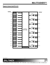
Example:
The MT110-102 in slot 4 has Input 1 connected
to all outputs. All outputs are on. Send the
command [?C4] to receive feedback status
similar to the following.
[(MT110-102C04)(VR690-0152-011C04)
(ON11111111C04)(MA0101010101010101C04)
(MX16x8C04)(VO3232323232323232C04)
(MU0C04)]
All status feedback is enclosed in brackets, “[ ]”.
Each data field within the status is enclosed in
parentheses. The first two characters identify
the status type. The last three characters are
the card’s ID.
MT110-102 = Card Model Number
VR690-0152-011 = Firmware version
ON11111111 = Output ON/OFF status
MA0101010101… = Matrix I/O connections
MX16x8 = Matrix Configuration
VO32323232… = Output Volume Levels
MU0C04 = Mute On/Off Status
The ON/OFF status line is read from left to right
as outputs 1-8. A ‘1’ indicates the output is on
and a ‘0’ indicates the output is off.