


Site Preparation – Operating Environment
990-1598B Smart-UPS® VT 10-30 kVA, 208/220 V Site Preparation and Installation Manual 13
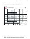
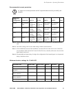
Recommended current protection
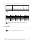
Note 1: If the available fault current of the installation is below 30 kA, a lower kAIC-rated breaker can be
used.
Note 2: For breaker settings, refer to below table listing available overload currents.
Note 3: If the available fault current of the installation is less than 1200 A for the 10 kVA and 15 kVA UPS
sizes, and below 2300 A for the 20 kVA and 30 kVA UPS sizes, a breaker (of the same value as for the
bypass input) can be used.
Note 4: Recommended maximum rating of a single-fuse configuration if the internal bypass is to be protected
during a load short-circuit.
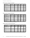
Minimum breaker settings for 10 kVA UPS
Note 1: For the output value, the short-circuit-level is indicated.
Note
AC output over-current protection and AC output disconnect must be provided by the
customer.
Dual/single
mains
configuration Connection 10 kVA 15 kVA 20 kVA 30 kVA Notes
Single Mains/bypass
input
35 A
breaker (30
kAIC)
60 A
breaker (30
kAIC)
80 A breaker
(30 kAIC)
125 A breaker
(30 kAIC)
Dual Mains input 35 A
breaker
(30 kAIC)
60 A
breaker
(30 kAIC)
80 A breaker
(30 kAIC)
125 A breaker
(30 kAIC)
1, 2
Dual Bypass input 35 A
breaker
(30 kAIC)
60 A
breaker
(30 kAIC)
80 A breaker
(30 kAIC)
125 A breaker
(30 kAIC)
1, 2
Any Output 35 A fast-
acting class
J fuse
60 A fast-
acting class
J fuse
80 A fast-
acting class
J fuse
125 A fast-
acting class
J fuse
3, 4
Overload Event Mains input Bypass input Output Duration Notes
Internal fault 2 kA 1.7 kA 14 kA <10 ms 1
800% overload bypass
operation
– 223 A 223 A 500 ms
150% overload normal/
battery operation
– – 42 A 30 s
125% overload normal/
battery operation
– – 35 A 60 s
Continuously 34 A 31 A 31 A
∞