


Electrical Installation – System-Electrical Information
26 Smart-UPS® VT 10-30 kVA, 208/220 V Site Preparation and Installation Manual 990-1598B
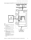
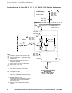
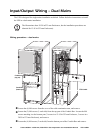
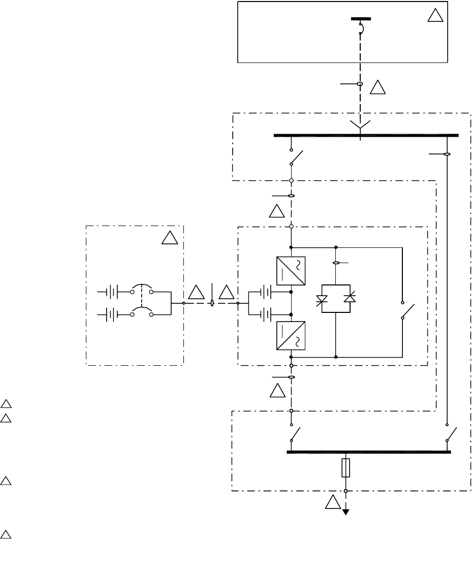
One-line diagram for Smart-UPS VT 10, 15, 20, 30kVA, 220V, 3 phase, single mains
10kVA, 26.2A
15kVA, 39.4A
20kVA, 52.5A
30kVA, 78.7A
10kVA, 26.2A
15kVA, 39.4A
20kVA, 52.5A
30kVA, 78.7A
10kVA, 26.2A
15kVA, 39.4A
20kVA, 52.5A
30kVA, 78.7A
10kVA, 26.2A
15kVA, 39.4A
20kVA, 52.5A
30kVA, 78.7A
10kVA, 26.2A
15kVA, 39.4A
20kVA, 52.5A
30kVA, 78.7A
F1, 3P
10kVA, 22.2A
15kVA, 33.3A
20kVA, 44.4A
30kVA, 66.6A
Q2/UOS)
4P
Q3(BPS)
4P
MBS
3P
Q1(UIS)
3P
1
2
2
2
2
2
5
8
MIB
10kVA, 35A.T.
15kVA, 60A.T.
20kVA, 80A.T.
30kVA, 125A.T.
XR Battery Cabinet
Utility source
(provided by others)
3PH 220Y/127V
4 wire + ground
Maintenance
Bypass
Panel
UPS
UPS System Output 10kVA, 15kVA,
20kVA and 30kVA
220V 3ph – 4 wire + ground or
127V 1ph – 2 wire + ground
Notes:
1. Must be 4 wire + ground WYE source provided by others.
2. Dashed lines between units (- - -) represent AC/DC cabling
provided by others.
3. Input overcurrent protection is based on 80% rating – any
deviation please contact APC.
4. AC Power cabling is 4 wire + ground at 208VAC 3-phase.
5. Separate conduits, 2 wire + ground
6. UPS input and output cables must be in separate conduits.
7. Power wiring and control wiring must be in separate
conduits
8. XR Battery Enclosure can be bayed to UPS. Baying kit has
to be purchased as an option.
XR Battery Enclosure is available without breaker with DC
fuses only. Up to 4 XR Battery Enclosures can be connected
to UPS to extend backup time.
9. Single mains installation is a default.
Dual Mains option requires custom entineering. Please refer
to APC Custom Engineering group and drawing# CEG-
SUVT10kF-SD for details.
10. Installation must comply with all applicable national and
local codes.
DC Input
Breaker