


990-1598B Smart-UPS® VT 10-30 kVA, 208/220 V Site Preparation and Installation Manual 29
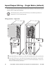
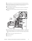
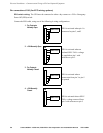
Loosen the (4) M4 screws (2 each side) from the bottom part of the Conduit Box and remove.
Punch 2 holes in the marked areas of the Conduit Box bottom to fit the size of the conduit pipes,
and reattach the Conduit Box bottom to the Enclosure, re-using the (4) M4 screws.
Install conduit pipes in the Conduit Box.
Run cables through the conduit pipes and the bottom of the Conduit Box, pull behind the bar
and up into the input/output area.
Reinstall the top part of the Conduit Box to the Enclosure, following reverse installation
procedures.
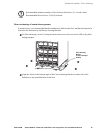
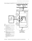
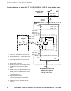
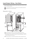
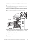
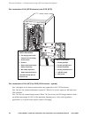
Attach input cable lugs to L1, L2 and L3 input busbars (left side in the UPS – on the front of the
busbar), using the provided M6 torx screws. Attach output cable lugs to L1, L2 and L3 output
busbars, using the provided M6 torx screws. Attach N x 2 where shown, using the provided torx
screws.
Attach Ground x 2 where shown, using the provided torx screws.
Fasten cables with cable ties.
Reinstall rear cover.
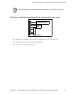
L
1
L
1
L
2
L
2
L
3
N
L
3
N
Ground
cables
Mains
input
cables
Neutral
Neutral
Output
cables