


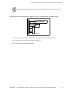

Electrical Installation – Communication Wiring to EPO and Optional Equipment
36 Smart-UPS® VT 10-30 kVA, 208/220 V Site Preparation and Installation Manual 990-1598B
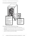
Pin connections J108 (for EPO wiring options)
EPO switch wiring. The UPS must be connected to either a dry contact or a 24V
DC
Emergency
Power Off (EPO) switch.
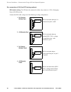
Connect the EPO cable, using one of the following 4 wiring configurations.
1
2
3
4
5
6
J108
EPO circuit
1
2
3
4
5
6
J108
1
2
3
4
5
6
J108
1
2
3
4
5
6
J108
1: Dry Contracts
Normally Open
2: +24V Normally Open
3: Dry Contacts
Normally Closed
4: +24V Normally
Closed
EPO circuit
EPO circuit
EPO circuit
EPO is activated when a
connection from pin 3 to pin 5
is opened
EPO is activated when pin 1 is
connected to pins 3, and 5
EPO is activated when an
isolated SELV 24V
DC
voltage
is supplied on pin 1 with
reference to pin 2.
EPO is activated when a SELV
24V
DC
voltage removed from
pin 3 with reference to pin 5