


Rev 1 MX28B-1200+27V PRODUCT MANUAL
15
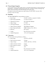
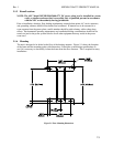
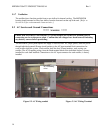
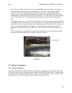
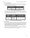
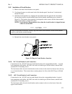
The AC input enclosure, located at the top rear of the MX28B housing, is provided with three pilot
holes in the top for attaching external conduit (Figure 5-4), and three 1-inch conduits exiting the
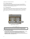
bottom for AC wire. AC wiring passing through the conduit will be routed through the access
opening in the AC input enclosure into the wiring area where a safety ground bar and rectifier input
terminal blocks are located. The terminal blocks are labeled as “L1” and “L2/N” for connection of the
two AC wires (Figure 5-3). Each terminal block represents connections for all 4 rectifiers in the
shelf.
The suggested wire size for L1, and L2 is #4 AWG rated at 105°C; however, the ambient temperature
and number of wires in a conduit must also be considered in accordance with NEC requirements. Be
sure to follow any local electrical wiring codes. Terminate the ground wire in the AC box at the top of
the unit to the ground terminal block. Continue to run the remaining two wires into the individual
conduits to each rectifier shelf. Connect them to L1, and L2 of the terminal block behind the access
plate.
If the AC input power is provided from a three-phase distribution panel, the circuit breaker positions
should be selected such that the load is balanced as much as possible.
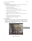
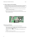
5.3 Battery Connections
5.3.1 Battery Disconnect
An external circuit breaker or fused disconnect (not supplied) is recommended in the positive line (located
at the battery end) to protect the cables from the battery to the MX28B DC power plant. The power plant
can monitor auxiliary contacts from this breaker. Selection of a circuit breaker or fuse for a battery string
should take into account maximum battery short circuit current and cable sizing.
Figure 5-4
Pilot holes (3)