


MX28B-1200+27V PRODUCT MANUAL Rev 1
16
5.3.2 Cable Sizing Considerations
The battery cable(s) should be sized sufficiently large to limit the voltage drop from the MX28B DC
power plant to the battery during charging per system design requirements. The cable(s) must also carry
the full load current during battery operation. If assistance is required to determine the necessary cables
for the application, contact your sales representative or APC.
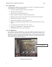
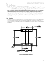
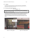
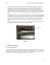
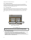
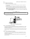
5.3.3 Connecting the Cables
The battery cable connections are located at the top rear of the unit as shown in Figure 5-5. The battery
negative (return bus) and battery positive (+24V) buses each provide two sets of 3/8”-16 holes on a double
pattern one-inch and 1 ¾-inch centers for connecting two-hole battery cable lugs. Connect the battery
cables as applicable using 3/8”-16 bolts (not provided) and tighten them with a torque wrench to 200 in-
lbs.
***** CAUTION *****
Make certain that the battery polarity is correct when making connections to the Model
MX28B DC power plant. Incorrect connection could cause severe equipment damage.
5.4 DC SYSTEM GROUNDING
THE NEGATIVE LOAD CONNECTION (RETURN BUS) FOR THE POWER PLANT MUST
BE CONNECTED TO THE FACILITY MASTER STATION GROUND. THE
CONNECTION SHOULD BE MADE ON THE RETURN BUS IN THE BASE UNIT
DISTRIBUTION AREA. DETAILS FOR THIS CONNECTION SHOULD BE PROVIDED IN
THE SITE ELECTRICAL GROUNDING PLANS.
Figure 5-5 Battery Connections
Battery Negative (-)
Battery Positive (
+
)