


Rev 1 MX28B-1200+27V PRODUCT MANUAL
9
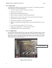
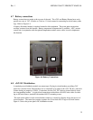
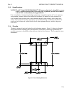
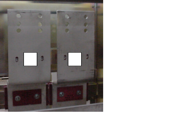
Figure 4.4 Battery Connections
4.7 Battery connections
Battery connections are made at the top rear of the unit. The +24V and Battery Return buses each
provide two sets of 3/8”-16 holes on 1 inch or 1 ¾ inch centers for connecting two-hole battery cable
lugs. Refer to Figure 4-4.
A battery disconnect breaker is required external to this equipment. The power plant can monitor
auxiliary contacts from this breaker. Battery temperature compensation is available. APC’s master
control unit, in conjunction with the optional temperature monitor sensor cable, is used to implement
this function.
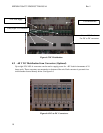
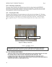
4.8 +24V DC Distribution
A standard power distribution module can mount up to 38 plug-in circuit breakers providing +24V
power for customer loads. Each breaker row is connected at its center to the +24V DC bus, with each
column having an ampacity of 300A. Connections for the +24V DC loads are located directly above
the corresponding breaker. A typical load connection would utilize a #6 AWG wire with a two-hole
lug on 5/8-inch centers, attached with standard #10-32 mounting screws.
The load return cables for each circuit breaker connect to a return bus directly above the top row of
circuit breakers. The return bus contains a pattern for 40 two-hole #10-32 lugs on 5/8-inch centers.
Figure 4-5 shows the power plant’s DC distribution section.
- +