


MX28B-1200+27V PRODUCT MANUAL Rev 1
26
The default passwords for level 1 and level 2 are “1111” and “2222”, respectively. There are no
alternate passwords or “backdoors” for accessing the system. A forgotten password may require a
new master controller board, at customer expense.
System control parameters are stored in non-volatile memory and will not be erased when power is
removed for the master control unit. However, if a new program EPROM is installed or a different
device model selected, the system control parameters will be re-initialized to the factory default
settings.
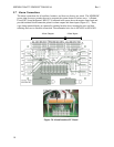
Eleven LEDs are provided on the front panel of the control unit to indicate system status. Three
LEDs grouped together vertically provide overall system status; they are “MAJOR”, “MINOR”, and
“NORMAL”, indicating the presence of a major alarm, a minor alarm, or normal operation. The
other eight LEDs correspond to the active state of each of the alarm output relays and are labeled
“ALM1”···“ALM6”, “MIN”, and “MAJ”.
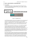
6.2 SNMP Interface
In addition, the unit’s controller incorporates a 10-base T Ethernet connection to allow remote access
to the system signals, and remote control of certain aspects of its operation. APC’s Manual #991-
0181 in the form of a CDRom will allow users to set up interface with the user’s Information
Technology System. Simple Network Management Protocol (SNMP) version 1 is supported along
with telnet protocol.
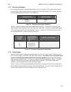
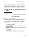
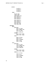
6.3 External Alarm Inputs
The four external alarm inputs (also referred to as “Input Relay Alarms”) can be assigned a priority
and routed or “mapped” to alarm output relays. Available assignments are “Ignore”, “Major”,
“Minor”, and “Relay 1” ··· “Relay 6”. Screens for making the assignments are located at
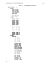
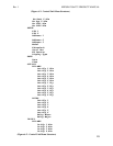
[SYSTEM/IN-RLY/RLY-MAP]. This special menu notation is explained with an example in
section 6.4
A user defined name or “alias” may also be assigned to each of these input alarms. Screens for
making these assignments are located at [SYSTEM/IN-RLY/ALIAS]. For information on wiring
connections to these inputs refer to Section 5.7.1.
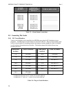
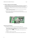
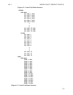
6.4 Alarm Output Relays
There are eight alarm output relays designated Relay 1 through Relay 6, Minor, and Major,
respectively. Various system parameters may be programmed to activate any of these alarm relays
when set thresholds are exceeded or specific conditions occur. The first six relays can also be
assigned a priority and routed or “mapped” to other output alarm relays. Available assignments are
“Ignore”, “Major”, “Minor”, and “Relay 1” ··· “Relay 6”. Screens for making these assignments
are located at [SYSTEM/OUT-RLY/RLY-MAP]. This feature makes it possible for a single alarm
condition to activate multiple alarm output relays including the Minor or Major alarm relay. A user
defined name or “alias” may also be assigned to each of the eight output relay alarms. Screens for
making these assignments are located at [SYSTEM/OUT-RLY/ALIAS]. For information on
making wiring connections to the alarm output relays refer to Section 5.7.2.