


MX28B-400 +24V Product Manual
990-9218 25
6. SETUP, ADJUSTMENTS, AND OPERATION
6.1 User Interface
The MX28B control unit provides a user interface designed with a hierarchical menu that can be
viewed on the 32-character display by “navigating” with the “ ” (left), “ ” (right), “ ” (up),
and “ ” (down) arrow keys located on the front panel. The selected item on the display is
identified by the cursor cycling beneath its characters.
The “M” (modify) key and the arrow keys are used to set parameters and text to customize the
system operation for a specific application. Items that can be modified have "m+" in the upper
right corner of the display. (If a security level higher than the one presently set is required to
modify the parameter, "s+" is displayed instead of “m+”.) Status, alarms, and information
screens have "+" in the upper right corner of the display (or “#” in the case of rectifier
information screens) and can not be modified. When ac power is initially applied, there is a 60-
second period during which no alarms are reported.
Pressing the "M" key on the front panel will change the "m+" to "M+", indicating that the
parameter can now be changed using the arrow keys. Some parameters can be changed to other
predefined selections by pressing the up or down arrow keys to display an alternative selection.
These parameters can be recognized after the “M” key is pressed by the cursor cycling beneath
the characters of the selection. For other parameters, such as text and most numeric values, after
the “M” key is pressed the cursor will be displayed under an individual character. The right or
left arrow key is used to position the cursor below the character to be changed and the up or
down arrow key is used to "spin" the digit or letter to the desired value. When the desired
changes have been made to an individual parameter screen, the “M” key is pressed again; the
“M+” changes back to “m+” and the new entry is stored in memory.
If the user plans to make any changes to system parameters, the first item that should be verified
or entered is the appropriate password for the security level required for the parameters to be
modified. Security level 2 enables modification of all variable system parameters, level 1
permits modification of some parameters; no security is required for viewing status items. The
security level password is entered through the “PIN” screen. If no front panel keys are pressed
for 60 minutes, the active
password reverts to “0000” and “█APC█” begins to move about the
display. Pressing any key returns the display to normal; the password must be re-entered if
system parameters require changes.
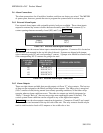
Eleven LEDs are provided on the front panel of the control unit to indicate system status. Three
LEDs grouped together vertically provide overall system status; they are “MAJOR”, “MINOR”,
and “NORMAL”, indicating the presence of a major alarm, a minor alarm, or normal operation.
The other eight LEDs correspond to the active state of each of the alarm output relays and are
labeled “ALM1”∙∙∙“ALM6”, “MIN”, and “MAJ”.
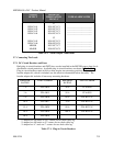
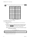
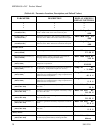
6.2 External Alarm Inputs
The four external alarm inputs (also referred to as “Input Relay Alarms”) can be assigned a
priority and routed or “mapped” to alarm output relays. Available assignments are “Ignore”,
“Major”, “Minor”, and “Relay 1” ∙∙∙ “Relay 6”. Screens for making the assignments are
located at [SYSTEM/IN-RLY/RLY-MAP]. A user defined name or “alias” may also be
assigned to each of these input alarms. Screens for making these assignments are located at