


MX28B-400 +24V Product Manual
990-9218 21
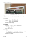
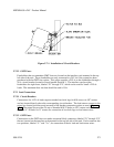
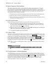
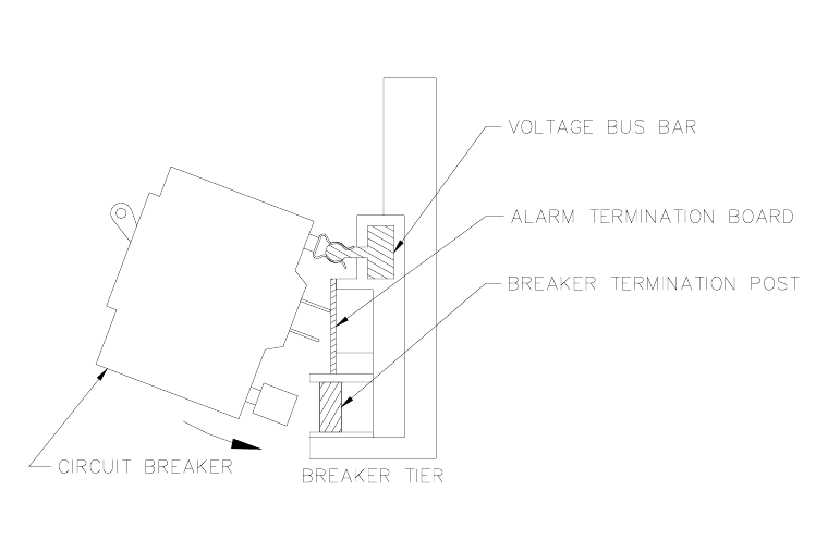
Figure 5.7-1. Installation of Circuit Breakers
5.7.2.2 GMT Fuses
Fuseholders that accommodate GMT fuses are located on the interface card mounted in the top
left side of the unit. These fuseholders are only connected to +24V dc if the system has been
purchased with the GMT fuse option. This option supplies +24V dc to the fuseholders through a
50 A. circuit breaker located in circuit breaker Position 1. The interface card provides
fuseholders for eight fuses, labeled “F1” through “F8”, which can be used for small +24V dc
loads. The maximum fuse size that should be used is 10A.
5.7.3 Load Connections
5.7.3.1 Circuit Breakers
Connections for +24V dc loads require standard two-hole lugs for #10 screws on 5/8” centers
and are located directly above the corresponding circuit breaker. The load returns connect to the
return bus located just above and rearward of the breaker connection points as seen in Figure
5.7-1. The return bus provides 24 sets of threaded #10-32 holes on 5/8” centers and four sets of
threaded ¼”-20 holes on ¾” centers for connection of two-hole lugs on load return wires.
5.7.3.2 GMT Fuses
Connections to the GMT fuses are made at terminal block connectors labeled “F1” through “F8”
that are located on the interface card mounted in the top left side of the unit. Each connector has
two positions, labeled “V-” and “V+”, for connection of the dc load and load return wires.