


MX28B-400 +24V Product Manual
12 990-9218
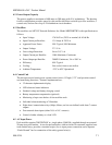
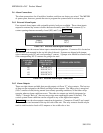
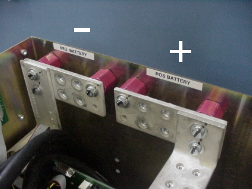
4.6 Battery connections
Top entry battery connections are made at the top rear of the unit (see Figure 4.6-1). The
voltage and return buses each provide two sets of threaded 3/8”-16 holes on one-inch centers for
connecting two-hole battery cable lugs.
A battery disconnect breaker is required external to this equipment. The power plant can
monitor auxiliary contacts from this breaker.
Battery temperature compensation is available. APC’s standard temperature monitor sensor and
cable is used to implement this optional function.
Figure 4.6-1. Battery Cable Connection Locations
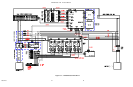
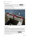
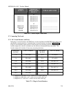
4.7 DC Distribution
A standard 24-position plug-in circuit breaker tier provides power distribution. The breaker tier
is connected at its center to the dc distribution bus, and each side has an ampacity of 300A.
Connections for 27V dc loads, requiring standard #10-32 two-hole lugs on 5/8-inch centers, are
located directly above the corresponding breaker. The load returns connect to the return bus,
which accommodates 24 two-hole #10-32 lugs on 5/8-inch centers, and four two-hole ¼”-20
lugs on ¾-inch centers. The return bus also provides a pair of threaded 3/8”-16 holes on 1-inch
centers for connection of a cable to the master station ground.
Figure 4.7-1 shows the power
plant’s dc distribution section with the front cover removed.
Eight GMT fused outputs are also available as an option. This option uses one of the 24
available circuit breaker positions.