


MX28B-400 +24V Product Manual
16 990-9218
Prior to installation, drawings, floor loading requirements, external alarm points, ac service
entrance, and grounding schemes should all be checked and confirmed. If batteries are to be
mounted in a room separate from the power plant, careful attention should be paid to battery
cable voltage drop effects. Environmental operating temperatures and ventilation/cooling
considerations should also be noted, not just for the power system but for all other equipment
that may reside in the power room area.
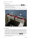
5.1.6 Mounting
Both front mounting on standard 23-inch rails and optional wall mounting are available.
5.1.7 Ventilation
The rectifiers have fans that provide front to rear airflow for internal cooling. The MX28B
housing should mounted such that there is free airflow to the front, top, and bottom of the unit.
[Refer to Section 4.9 for environmental characteristics.]
5.2 AC Service and Ground Connections
***** WARNING *****
Ensure that all of the dc and external ac circuit breakers are in the OFF position prior to
connecting service to the power plant. Confirm that all voltages have been removed
including any battery sources before proceeding.
The MX28B dc power plant requires the supply of 208/220/240V ac, single-phase, 50/60 Hz
power through individual external 20-amp two-pole circuit breakers to the ac input terminal
block connections for each rectifier in the system. (The ac wiring, from the ac input terminal
block connections to the hot-pluggable ac input connector for each rectifier, is factory installed.)
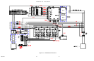
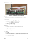
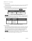
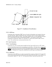
The ac input enclosure, located at the top right rear of the MX28B housing, is provided with two
one-inch conduit entry holes and an access cover. Inside, a terminal strip(s) for ac input power
connection and a separate “Earth Ground” bar for connection of the safety ground wire(s) are
provided. The terminal block(s) is labeled as Position 1 through Position 4 (Position 1 through
Position 8 for the 400-amp unit) with each position having inputs designated “L1” and “L2” for
connection of the two ac wires. Positions 1-4 correspond to the top rectifier shelf positions from
left to right. Positions 5-8 are applicable to the 400-amp unit only and correspond to the lower
rectifier shelf positions from left to right.
The suggested wire size is #10 AWG rated at 90°C or higher; however, the ambient temperature
and number of wires in a conduit must also be considered in accordance with NEC
requirements. It is suggested that feeds for four rectifiers (8 wires) and one safety ground wire
be run in a one-inch conduit; however, be sure to follow any local electrical wiring codes.
If the ac input power is provided from a three-phase distribution panel, the circuit breaker
positions should be selected such that the load is balanced as much as possible.