


Magnum VS –48 Vdc User Manual Page 19
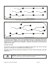
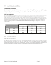
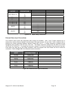
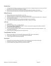
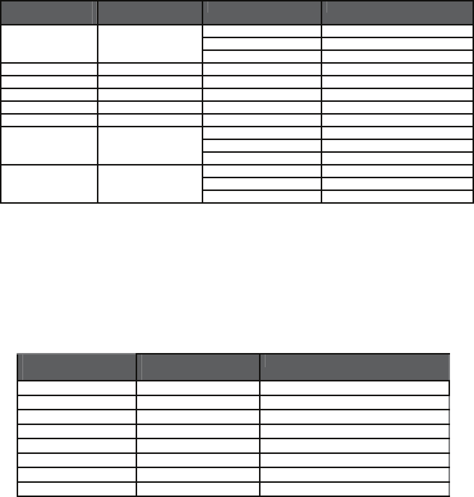
RELAY
OUTPUT
J 411 TERMINAL
DESIGNATIONS
RELAY ALIAS OUTPUT RELAY NOTES
NO
OUT RELAY #1 C
NC
OUT RELAY #2 N/A
OUT RELAY #3 N/A
OUT RELAY #4 N/A
OUT RELAY #5 N/A
OUT RELAY #6 N/A
NO N/A
MINOR C N/A
NC N/A
NO N/A
MAJOR C N/A
NC N/A
Figure 2.9-2 Output Relay Connections
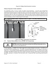
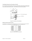
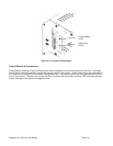
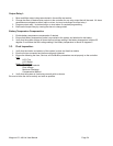
External Alarm Input Connections
Four external alarm inputs with assignable relay outputs are available. User 1 and 2 inputs respond only to
external dry contact closures between normally open (NO) and common (C) and User 3 and 4 respond only to
external dry contact openings between normally closed (NC) and C. A Wago connector is located on the
backplane card mounted in the left rear of the unit. The Wago connectors accept wires 26 AWG to 20 AWG
(0.129 mm
2
to 0.518 mm
2
). To connect the user input, remove ¼ in (6 mm) of insulation from the end of the wire.
Push down the white tab on the Wago connector, insert the stripped wire and release the tab to make the
connection. Refer to Figure 2.9-1 for backplane board connections.
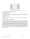
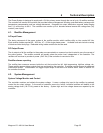
EXTERNAL ALARM
INPUT
J412 TERMINAL
DESIGNATIONS
USER ALARM NOTES
#1 NO USER1NO
#2 NO USER2NO
#3 NC USER3NC
#4 NC USER4NC
#1 C USER1C
#2 C USER2C
#3 C USER3C
#4 C USER4C
Figure 2.9-3 External User Input Connections