


Magnum VS –48 Vdc User Manual Page 28
Battery Protection
An external disconnect should be mounted at the battery string to protect the system from the high energy stored in
the battery if a short occurs. The battery LVD will not be energized until a battery string is installed with the proper
polarity and the battery disconnect switch is turned on. The battery connections are to be used for the battery only.
Do not attach loads to the battery connections or erroneous battery current will be reported. The controller reports
Battery high and low voltage alarms and LVD alarms.
Battery Temperature Monitoring
Battery temperature is monitored using a probe attached to the battery casing. The controller reports Battery high
and low temperature alarms.
Battery Temperature Compensation
The Battery Float Voltage is set to the value recommended by the battery manufacturer in order to maintain correct
battery charge at 25ºC. As temperature rises, electrochemical activity in a battery increases. Similarly, as
temperature falls, electrochemical activity in a battery decreases. As temperature rises, charging voltage should be
reduced to prevent overcharge and possible thermal runaway. As battery temperature falls, voltage is increased to
prevent undercharge. The dc power system uses Battery Temperature compensation to change output voltage to
compensate for temperature changes monitored at the battery temperature probe. This temperature compensation
function is programmed into the controller using the compensation parameters settings. Default settings can be
changed to values recommended by the particular battery manufacturer. The controller will not allow the system
voltage to be adjusted beyond the range of –47 Vdc to –56.5 Vdc.
Battery Low Voltage Disconnect
In order to prevent damage to the battery due to deep discharge, the dc power system has hardware and software
support for a battery Low Voltage Disconnect (LVD). When the battery voltage reaches the threshold set by the
LVD 1 Trip Voltage setting during discharge, the dc power system will activate the LVD contactor to disconnect the
battery from the system. The LVD will remain open until ac power is restored to the system and the bus voltage
reaches the level defined by the LVD 1 Reset Voltage variable. The LVD control can be disabled on the LVD
parameters screen in the controller.
NOTE: The LVD is normally energized and must be commanded to open. This assures that the LVD will remain
closed even if the controller fails or is removed.
The LVD will not be energized until a battery string is installed with the correct polarity and the battery disconnect
switch is turned on. This will prevent the battery from being hooked up backwards and damaging the rectifiers
and/or the loads. Once the battery is connected correctly and the LVD is closed, the LVD will open only in low
voltage situations. The battery connections are to be used for the battery only.
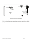
Counter Electro-Motive Force Module Connections
A connection is provided to connect a Counter Electro-Motive Force (CEMF) Module. A CEMF is a semiconductor
device connected in series with a battery and used to reduce the voltage to loads that cannot tolerate the “normal”
main cell voltage. The CEMF cells are automatically switched out of the circuit when the discharge voltage drops to
a predetermined level and are automatically switched back into the circuit when the battery approaches its normal
float value.