


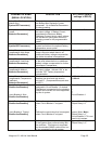

Magnum VS –48 Vdc User Manual Page 31
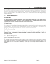
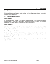
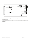
J1
1
11
10 1
65
J5
J3
J13
J9 J8
J2
J12
J4
DB9 - RS232 Port
MAJOR
DC GOOD
MINOR
OUT RLY
VR1
J10
J11
System Voltage Select
SNMP Interface
Vtrim Dropout
Parameter Change LockoutFirmware Change
Positive Test Jack
Negative Test Jack
Display Contrast
"HEARTBEAT" LED
Display Interface
Display Backlight Power
1
J6
Keypad Interface
Figure 5.2-1 Controller Card Jumper Locations
Controller Module
All status monitoring and/or parameter changes are made using a computer connected to the Magnum VS system
over an (10/100 Base-T) Ethernet network or directly connected via a serial cable. Refer to Figure 0-1 for the front
panel layout.