


Magnum VS –48 Vdc User Manual Page 29
4.5. Controls and Indicators
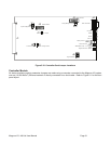
Controller Module
All status monitoring and/or parameter changes are made using a computer connected to the Magnum VS system
over an (10/100 Base-T) Ethernet network or directly connected via a serial cable. Refer to Section 5 for additional
information.
There are five visual indicators (LEDs) on the Controller Module. The Major LED (Red) is on when the Major Relay
is de-energized. The Major Relay is energized when there is no alarm. This will produce a major relay output even
when all power is lost. The Minor LED (Yellow) is on when the Minor Relay is energized. The Out Relay LED
(Yellow) is on when the Out Relay is energized. The DC OK LED (Green) is on when the voltage is between 50
and 57 Vdc. The green LED behind the front panel is slowly flashing when the controller is processing data.
4.6. Alarm Outputs (Output Relays)
There are three alarm output relays designated Out Relay 1, Minor, and Major. Various system parameters may be
programmed to activate any of these output relays when set thresholds are exceeded or specific conditions occur.
Out Relay 1 can also be routed or “mapped” to “Out Relay 1-6,” “Minor Relay,” “Major Relay” or “Ignore.” This
feature makes it possible for a single alarm condition to activate multiple alarm output relays including the Minor or
Major alarm relay. For information on making wiring connections to the alarm output relays refer to Section 2.9
In addition to the output relays described above there are 5 outputs that do not support actual hardware. These are
called Output Relay 2 through 6. While the relay hardware is not available, the programming can still be used to
provide more detailed information through the network management card. Using the actual relay 1 and the 5 virtual
relays 2-6, six different parameters can be alarmed with unique messages through the network management card.
Various system parameters may be programmed to activate any of these output relays when set thresholds are
exceeded or specific conditions occur. Relay 2-6 can also be routed or “mapped” to “Out Relay 1-6,” “Minor Relay,”
“Major Relay” or “Ignore.”
Out Relay 1-6 can be renamed using the Relay Alias setup screen. Each relay name can be up to sixteen
characters in length. This name will appear in the messages generated by the network management card. This
can be used to give specific information on the exact nature of the active alarm.
4.7. External Alarm Inputs (User Input)
The Controller can monitor any external device that uses a voltage free (“dry contact”) switch or relay to output
status information. The four external user inputs can be routed or “mapped” to alarm output relays. Available
assignments are “Ignore”, “Major”, “Minor”, and “Out Relay 1.” For information on wiring connections to these
inputs refer to Section 2.9
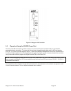
4.8. Network Management Card - Local & Remote Monitoring
The Magnum VS controller includes an APC AP9617 Network Management Card which allows both local and
remote access to the power system. The AP9617 is a web-based management product that uses multiple, open
standards such as Telnet, HTTP, and SNMP to provide full management of supported devices. The following is a
list of some of this Management Card’s features:
- Provides a Data Log accessible by FTP or a Web browser.
- Provides an Event Log accessible by Telnet, FTP, or a Web browser
- Detects connection speed of 10/100 MB per second.
- Generates Email notifications for DC Power Plant events and system events.
-Limits SNMP traps and Email notifications based on the severity level of the DC Power Plant or system events
The Management Card has two internal interfaces (control console and Web interface) which provide menus with
options that allow you to manage the DC Power Plant and the Management Card. The Management Card’s SNMP
interface also allows you to use an SNMP browser with the PowerNet® Management Information Base (MIB) to
manage the DC Power Plant.