


Introduction
4
NetLinx Integrated Controllers
NI-2000 Specifications (Cont.)
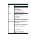
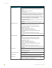
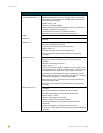
Digital I/O (Port 9) • Four-channel binary I/O port for contact closure
• Each input is capable of voltage sensing. Input format is software
selectable.
• Interactive power sensing for IR ports
• Channel range = 1-4
• All inputs are assigned to respective IR/Serial ports for "automatic" power
control through the use of software commands. Power control is provided
via commands such as: ’PON’, ’POF’, ’POD’, ’DELAY’, I/O Link etc.).
• Contact closure between GND and an I/O port is detected as a PUSH
• When used as voltage input - I/O port detects a low signal (0- 1.5 VDC) as
a PUSH and a high signal (3.5 - 5 VDC) as a RELEASE
• When used as an output - each I/O port acts as a switch to GND and is
rated at 200 mA @ 12 VDC
• One 6-pin 3.5 mm mini-Phoenix (female) connector provides I/O port
termination
IR/Serial (Ports 5-8) • Four IR/Serial control ports support high-frequency carriers up to
1.142 MHz
• Each output is capable of two electrical formats: IR or Serial
• Four IR/Serial data signals can be generated simultaneously.
• Channel range = 1-32,767
• Channels 1-128 (output): IR commands
• Channels 129-253: used as reference channels
• Channel 254 (feedback): Power Fail (used with 'PON' and 'POF'
commands)
• Channel 255 (feedback): Power status (when IO Link is set)
• One 8-pin 3.5 mm mini-Phoenix (female) connector provides IR/Serial port
termination
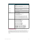
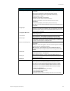
IR/Serial (Ports 5-8) • Four IR/Serial control ports support high-frequency carriers up to 1.142
MHz
• Each output is capable of two electrical formats: IR or Serial
• Four IR/Serial data signals can be generated simultaneously
• Channel range = 1-32,767
• Channels 1-128 (output): IR commands
• Channels 129-253: used as reference channels
• Channel 254 (feedback): Power Fail (used with 'PON' and 'POF'
commands)
• Channel 255 (feedback): Power status (when IO Link is set)
• One 8-pin 3.5 mm mini-Phoenix (female) connector provides IR/Serial port
termination
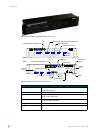
Program port • Single RS-232 DB9 connector (male) can be connected to a DB9 port on a
computer; used with serial commands, NetLinx programming commands,
other DB9 capable devices, and to upload/download information from the
NetLinx Studio 2.2 program.
Configuration DIP switch • Use this DIP switch to set the communication parameters for the rear
RS232 Program port.
ID pushbutton • Sets the NetLinx ID (D) assignment for the device.
• The D notation is used to explicitly represent a device number.
Ethernet port • Single RJ-45 port for 10/100 Mbps communication. The Ethernet Port
automatically negotiates the connection speed (10 Mbps or 100 Mbps) and
whether to use half duplex or full duplex mode.