


Connections and Wiring
26
NetLinx Integrated Controllers
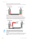
IR/Serial Connections and Wiring
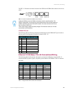
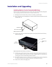
You can connect up to eight IR- or Serial-controllable devices to the IR/Serial connectors on the
rear of the NI-4000 and NI-3000 and up to four on the NI-2000 (FIG. 16). These connectors accept
an IR emitter (CC-NIRC) that mounts onto the device's IR window, or a mini-plug (CC-NSER) that
connects to the device's control jack. You can also connect a data 0 - 5 VDC device. These units
come with two CC-NIRC IR emitters (FG10-000-11).
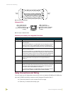
The IR/Serial connector wiring specifications are listed in the following table.
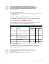
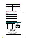
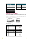
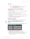
I/O Port Wiring Specifications
NI-4000 and NI-3000
I/O Port Wiring Specifications NI-2000
Pin Signal Function Pin Signal Function
1 GND Signal GND 1 GND Signal GND
2 I/O 1 Input/Output 2 I/O 1 Input/Output
3 I/O 2 Input/Output 3 I/O 2 Input/Output
4 I/O 3 Input/Output 4 I/O 3 Input/Output
5 I/O 4 Input/Output 5 12 VDC PWR
6 I/O 5 Input/Output
7 I/O 6 Input/Output
8 I/O 7 Input/Output
9 I/O 8 Input/Output
10 12 VDC PWR
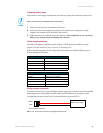
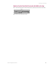
FIG. 16 IR/SERIAL (male)
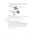
IR/Serial Connector Wiring Specifications
No. NI-4000/3000 Port NI-2000 Port Signal Function
19 5 GND (-)
Signal 1 (+)
210 6 GND (-)
Signal 2 (+)
311 7 GND (-)
Signal 3 (+)
412 8 GND (-)
Signal 4 (+)
513 N/A GND (-)
Signal 5 (+)
614 N/A GND (-)
Signal 6 (+)
715 N/A GND (-)
Signal 7 (+)
816 N/A GND (-)
Signal 8 (+)
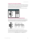
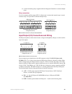
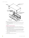
IR / SERIAL (Ports 5-8)
IR / SERIAL (Ports 9-16)
8 76 45 321
4 23 1
NI-4000/NI-3000 IR/Serial connector
configuration (Port 9-16)
NI-2000 IR/Serial connector
configuration (Port 5-8)