


Connections and Wiring
23
NetLinx Integrated Controllers
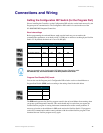
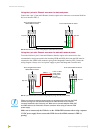
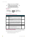
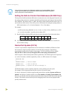
The FIG. 11 illustrates the relative location of the ICSNet and ICSHub Out connectors on the rear
panel.
ICSHub OUT port
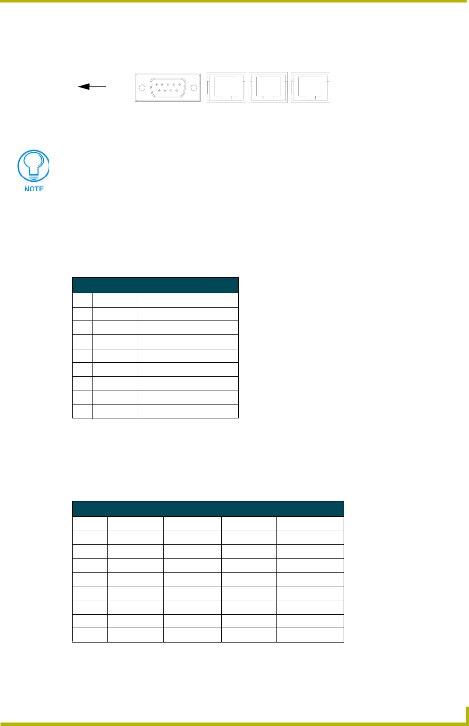
The following table describes the pinout/signal information for the ICSHub OUT port located on
the rear panel of the Integrated Controller (as shown in FIG. 11).
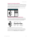
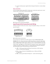
Ethernet 10/100 Base-T RJ-45 Connections/Wiring
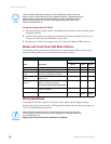
The following table lists the pinouts and signals associated to the Ethernet connector. FIG. 12
describes the RJ-45 pinouts, signals, and pairing for the Ethernet 10/100 Base-T RJ-45 connector
and cable.
FIG. 12 diagrams the RJ-45 cable and connectors.
FIG. 11 Location of ICSNet and ICSHub Out connectors
PORT 1
Ports
ICSNet
ICSNet ICSHub Out
Unlike the ICSNet ports, the ICSHub connections require a specific polarity. The
IN/OUT configuration, on the hub ports, was implemented to use the same cables as
ICSNet, but these ports need TX and RX crossed. You must connect an OUT to an
IN, or an IN to an OUT port.
This is done simply to keep the polarity straight. The Hub bus is still a bus. All Hub
connections are bi-directional.
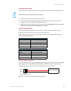
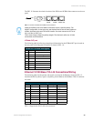
ICSHub OUT Pinouts and Signals
Pin Signal Color
1 RX + orange-white
2 RX - orange
3 ------ ------
4 ------ ------
5 ------ ------
6 ------ ------
7TX + brown-white
8TX - brown
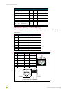
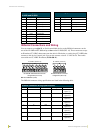
Ethernet RJ-45 Pinouts and Signals
Pin Signals Connections Pairing Color
1 TX + 1 --------- 1 1 --------- 2 Orange-White
2 TX - 2 --------- 2 Orange
3 RX + 3 --------- 3 3 --------- 6 Green-White
4 no connection 4 --------- 4 Blue
5 no connection 5 --------- 5 Blue-White
6 RX - 6 --------- 6 Green
7 no connection 7 --------- 7 Brown-White
8 no connection 8 --------- 8 Brown