


ADSP-2186
–12–
REV. 0
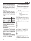
The EZ-ICE
®
* connects to your target system via a ribbon cable
and a 14-pin female plug. The female plug is plugged onto the
14-pin connector (a pin strip header) on the target board.
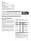
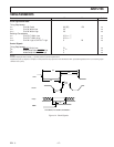
Target Board Connector for EZ-ICE
®
* Probe
The EZ-ICE
®
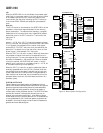
* connector (a standard pin strip header) is shown
in Figure 7. You must add this connector to your target board
design if you intend to use the EZ-ICE
®
*. Be sure to allow
enough room in your system to fit the EZ-ICE
®
* probe onto the
14-pin connector.
×
12
34
56
78
910
11 12
13 14
GND
KEY (NO PIN)
RESET
BR
BG
TOP VIEW
EBG
EBR
ELOUT
EE
EINT
ELIN
ECLK
EMS
ERESET
Figure 7. Target Board Connector for EZ-ICE
®
*
The 14-pin, 2-row pin strip header is keyed at the Pin 7 loca-
tion—you must remove Pin 7 from the header. The pins must
be 0.025 inch square and at least 0.20 inch in length. Pin spac-
ing should be 0.1 × 0.1 inches. The pin strip header must have
at least 0.15-inch clearance on all sides to accept the EZ-ICE
®
*
probe plug. Pin strip headers are available from vendors such as
3M, McKenzie and Samtec.
Target Memory Interface
For your target system to be compatible with the EZ-ICE
®
*
emulator, it must comply with the memory interface guidelines
listed below.
PM, DM, BM, IOM, & CM
Design your Program Memory (PM), Data Memory (DM), Byte
Memory (BM), I/O Memory (IOM) and Composite Memory
(CM) external interfaces to comply with worst case device tim-
ing requirements and switching characteristics as specified in
this DSP’s data sheet. The performance of the EZ-ICE
®
* may
approach published worst case specification for some memory
access timing requirements and switching characteristics.
Note: If your target does not meet the worst case chip specifica-
tion for memory access parameters, you may not be able to
emulate your circuitry at the desired CLKIN frequency. Depend-
ing on the severity of the specification violation, you may have
trouble manufacturing your system as DSP components statisti-
cally vary in switching characteristic and timing requirements
within published limits.
Restriction: All memory strobe signals on the ADSP-2186 (RD,
WR, PMS, DMS, BMS, CMS and IOMS) used in your target
system must have 10 kΩ pull-up resistors connected when the
EZ-ICE
®
* is being used. The pull-up resistors are necessary
because there are no internal pull-ups to guarantee their state
during prolonged three-state conditions resulting from typical
EZ-ICE
®
* debugging sessions. These resistors may be removed
at your option when the EZ-ICE
®
* is not being used.
Target System Interface Signals
When the EZ-ICE
®
* board is installed, the performance on
some system signals change. Design your system to be compat-
ible with the following system interface signal changes intro-
duced by the EZ-ICE
®
* board:
• EZ-ICE
®
* emulation introduces an 8 ns propagation delay
between your target circuitry and the DSP on the RESET
signal.
• EZ-ICE
®
* emulation introduces an 8 ns propagation delay
between your target circuitry and the DSP on the BR signal.
• EZ-ICE
®
* emulation ignores RESET and BR when single-
stepping.
• EZ-ICE
®
* emulation ignores RESET and BR when in Emu-
lator Space (DSP halted).
• EZ-ICE
®
* emulation ignores the state of target BR in certain
modes. As a result, the target system may take control of the
DSP’s external memory bus only if bus grant (BG) is asserted
by the EZ-ICE
®
* board’s DSP.