


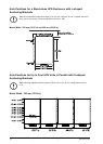
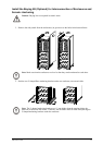
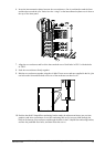
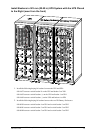
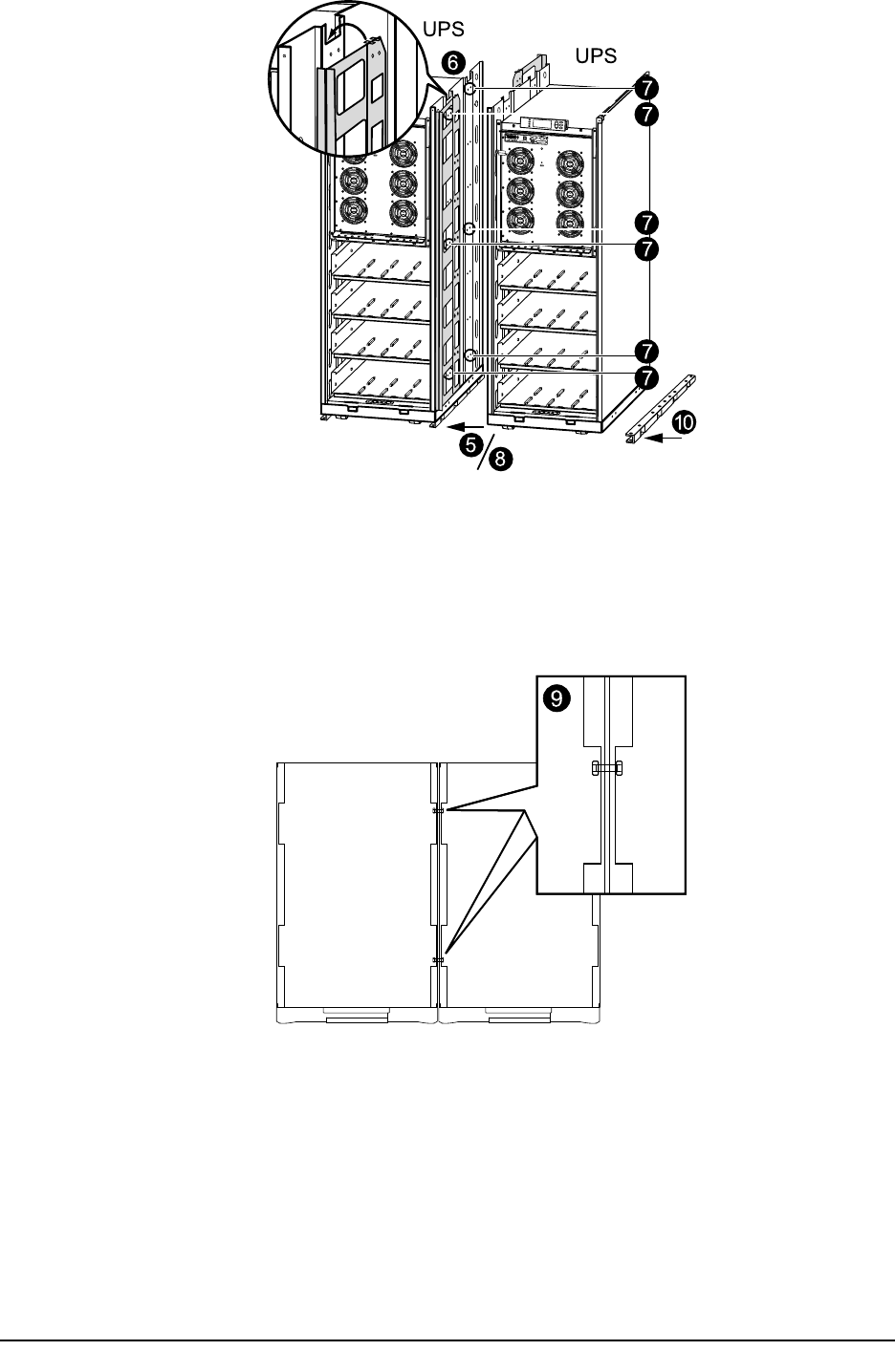
6. Insert the interconnection plates between the two enclosures. One is positioned toward the front
and the other toward the rear. Notice how the “wings” on the interconnection plates rest in slots at
the top of the inner panel.
10
5
8
6
7
7
7
7
7
7
UPS
UPS
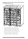
7. Align the two enclosures and level the three marked rows of bolt holes in UPS 1 with the holes
in UPS 2.
8. Push the two enclosures rmly together.
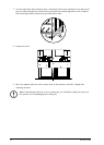
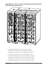
9. Bolt the two enclosures together using the six M6x25 mm screws and nuts supplied in the kit; join
one hole at the front and one hole at the rear of the enclosures on three levels.
10. Position the third U-shaped oor anchoring bracket under the adjacent enclosure (see previous
graphics) and insert a minimum of two oor anchoring M8 screws (not provided) through the
holes in the bottom of the enclosure and through the holes in the U-shaped oor anchoring bracket,
and into the predrilled oor holes, and then fasten the screws.
990-1957C-001
MGE™ Galaxy™ 3500 10-30 kVA 208/220 V Single and Parallel Installation
15