


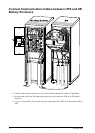
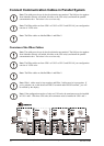
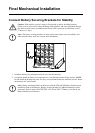

5. From the bottom of UPS 2, run the PBus cables to the slots on the left side of the enclosure and
up inside the panel.
6. Take out the PBus cables and leave these unattached.
7. Run the ABus cable from the maintenance bypass panel to the slots on the left side of the enclosure
and up inside the panel the same way as for the PBus cables.
8. Reattach the cable-inlet cover plates.
9. Fasten the cables with cable ties.
Note: Proceed the routing of cables into UPS 3 and UPS 4, if applicable.
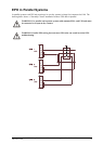
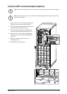
UPS Units Apart or Bayed Together with Conduits
Note: When enclosures are assembled with interconnection plates and bolted together, the
PBus cables can be run inside the enclosures and then only the ABus cable has to be run in
a conduit (if applicable).
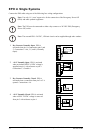
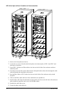
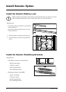
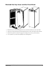
1. Remove the front panel (not shown).
2. Remove the top cover:
A. Loosen the six screws of the top cover (four at the front and two at the back).
B. Lift up from the back and push forward to free the cover.
C. Leave the cover unattached on top of the UPS.
2
A
A
3. Remove the conduit plate at the back of the UPS cover and drill holes centered in the small
pre-drilled holes. 2 cm (3/4 in) is recommended for conduits.
4. Run the ABus and the PBus cables through the conduit holes into the inside of the top cover on
UPS 1. Leave the cables on top of the UPS.
5. Attach conduits with 2 cm (3/4 in) ttings (not supplied).
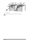
6. Run conduits with PBus cables to UPS 2. Pull the cables through the top cover conduit plate and
leave the cables on top of the UPS as shown.
7. Attach conduits to UPS 2 with 2 cm (3/4 in) ttings (not supplied).
8. Run the ABus cables (in conduits if applicable) to the maintenance bypass panel.
40
MGE™ Galaxy™ 3500 10-30 kVA 208/220 V Single and Parallel Installation
990-1957C-001