


Table of Contents
IMPORTANT SAFETY INSTRUCTIONS – SAVE THESE
INSTRUCTIONS ............................................................................................................... 1
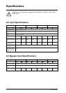
Specications................................................................................................................... 2
AC Input Specications.............................................................................................. 2
AC Bypass Input Specications .............................................................................. 2
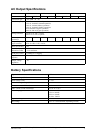
AC Output Specications .......................................................................................... 3
Battery Specications ................................................................................................ 3
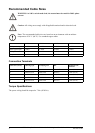
Recommended Cable Sizes ...................................................................................... 4
Connection Terminals................................................................................................ 4
Torque Specications................................................................................................ 4
Fuses and Breakers .................................................................................................... 5
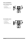
Single Utility/Mains System ....................................................................................... 5
Dual Utility/Mains System.......................................................................................... 5
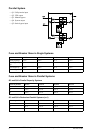
Parallel System.......................................................................................................... 6
Fuse and Breaker Sizes in Single Systems................................................................ 6
Fuse and Breaker Sizes in Parallel Systems.............................................................. 6
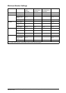
Minimum Breaker Settings ........................................................................................ 7
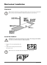
Mechanical Installation ............................................................................................... 8
Clearance ....................................................................................................................... 8
Level the Cabinet ......................................................................................................... 8
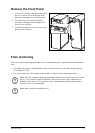
Remove the Front Panel ............................................................................................ 9
Floor Anchoring .......................................................................................................... 9
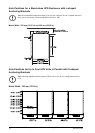
Hole Positions for a Stand-alone UPS Enclosure with L-shaped Anchoring
Brackets ....................................................................................................................10
Hole Positions for Up to Four UPS Units in Parallel with U-shaped Anchoring
Brackets ...................................................................................................................10
Connect Floor Anchoring Brackets to the UPS and XR Battery Enclosure for
Stability......................................................................................................................11
Remove the Battery Modules.....................................................................................12
Install the Baying Kit (Optional) for Interconnection of Enclosures and Seismic
Anchoring..................................................................................................................13
Install XR Battery Enclosures (Option)..............................................................16
Remove the Cable Landing Cover and Bottom Plates ......................................16
Connect Battery Power in Installations with Busbars .......................................17
Isolator Installation Principle.....................................................................................17
990-1957C-001
MGE™ Galaxy™ 3500 10-30 kVA 208/220 V Single and Parallel Installation
i