


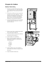
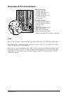
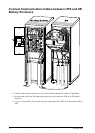
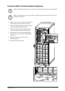
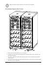
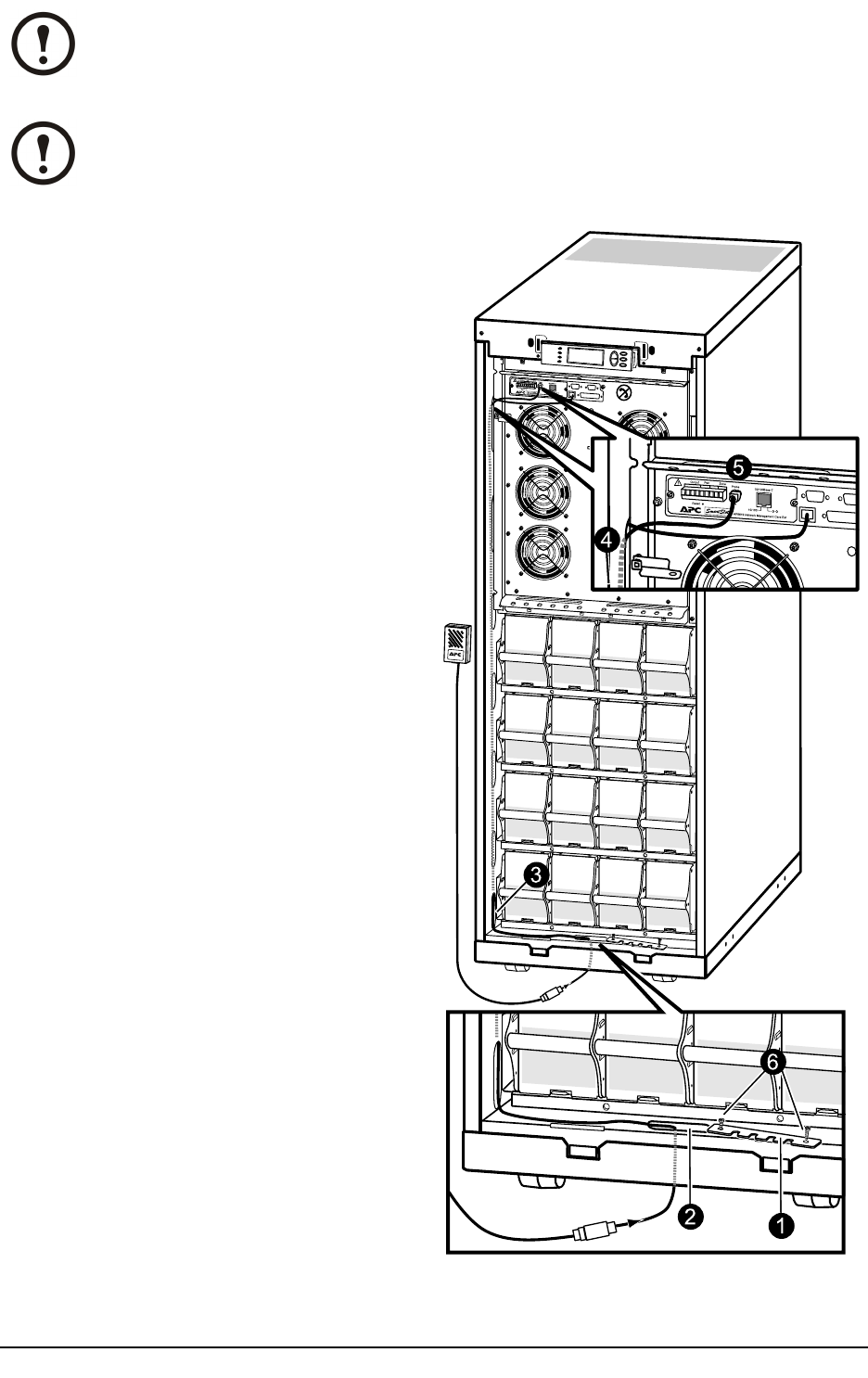
Connect APC Communication Options
Note: The cable routing of the power chute software and the temperature sensor is identical.
Note: The temperature sensor is provided in a plastic bag attached to the front of the UPS
behind the front panel.
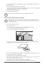
1. Remove the two screws from the cable-inlet at
the front and remove the cable-inlet plate.
2. Guide the cable through the hole in the bottom
plate and up through the cable-inlet.
3. Guide the cable through the side panel hole
and run the cable upwards inside the panel.
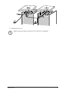
4. Pull the cable out of the side panel through
the hole closest to the Network Management
Card area.
5. Plug the cable into the probe socket /
PowerChute inlet.
6. Reattach the cable-inlet plate.
6
1
2
3
4
5
990-1957C-001
MGE™ Galaxy™ 3500 10-30 kVA 208/220 V Single and Parallel Installation
35