


User Manual version 2007
APOLLO 120/150 III
5-
65
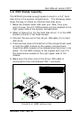
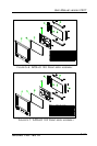
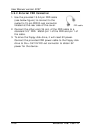
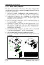
6. The touchscreen 5-pin flat cable should go through the
rectangle opening at the upper left side of the LCD holder,
then connect to the touchcreen controller.
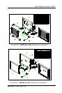
7. For APOLLO 150, the invertor now is to be fixed to the left
outward side of the chassis and have the invertor cable go
into the chassis through the cutout. Connect the other
end of the invertor cable to the motherboard’s INV1.
8. Connect the other end of the IR/LED cable to the IR/LED
board.