


Take Apart Screw Matrix - 2
Screw Matrix
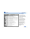
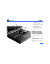
The screw matrix at left
shows the number and type
of screws installed in the top
and bottom case.
For a view showing the
screws and their locations
within the case, go to the
Exploded View chapter.
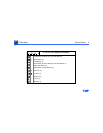
The next page shows the
display screws. (The
number of screws varies
with the size and
manufacturer of the
display.)
Bottom Case— Power Supply (1 top)
Bottom Case— I/O Panel (4)
0
1
1
8
3
8
5
8
1
2
3
4
1
4
Bottom Case—(2, long, in front)
Bottom Case— PC Cardcage (4, #6 Torx)
Top Case—Heat Sink (1 Phillips)
Scale = 1 inch
Bottom Case—(6, short)
(black)
Bottom Case— Standoff (1 under Power Supply)
Case Assembly Screws
Top Case— (1 between B&V controls) (2 by speaker grilles)
Top Case—Stiffener to Modem (1)
Top Case—Trackpad Switch Carrier (2)
Trackpad Hold Down (2) Control Button Cable (2)
Top Case—PC Eject Switch (2) Speakers (2 ea) Stiffener (2)
(silver)
Top Case—Heat Sink (1 Phillips)
Top Case—Hard Drive Bracket (4) Hard Drive Connector (2)
Bottom Case—Eject Arms (2) PMU Board (1)