


32 ASUS A7A266-E User’s Manual
3. HARDWARE SETUP
Connectors
3. H/W SETUP
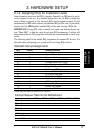
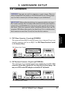
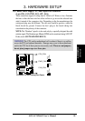
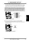
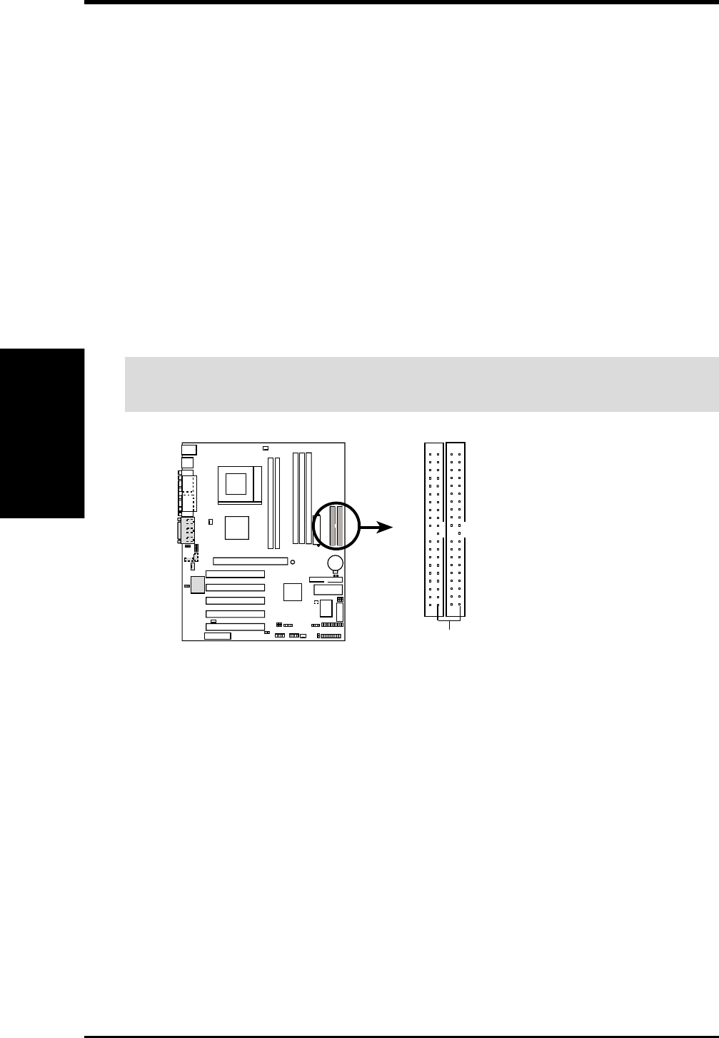
9) Primary (Blue) / Secondary IDE Connectors (Two 40-1pin IDE)
These connectors support the provided UltraDMA133/100 IDE hard disk ribbon
cable. Connect the cable’s blue connector to the motherboard’s primary
(recommended) or secondary IDE connector, and then connect the gray connector
to your UltraDMA133/100 slave device (hard disk drive) and the black connector
to your UltraDMA133/100 master device. It is recommended that non-
UltraDMA133/100 devices be connected to the secondary IDE connector. If
you install two hard disks, you must configure the second drive to Slave mode
by setting its jumper accordingly. Please refer to your hard disk documentation
for the jumper settings. BIOS now supports specific device bootup (see 4.6 Boot
Menu). (Pin 20 is removed to prevent inserting in the wrong orientation
when using ribbon cables with pin 20 plugged).
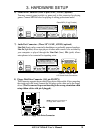
TIP: You may configure two hard disks to be both Masters with two ribbon
cables – one for the primary IDE connector and another for the secondary IDE
connector. You may install one operating system on an IDE drive and another on
a SCSI drive and select the boot disk through the BIOS.
IMPORTANT: UltraDMA133100/66 IDE devices must use a 40-pin 80-
conductor IDE cable for 133MB/s transfer rates.
0101
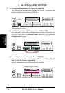
A7A266-E
A7A266-E IDE Connectors
NOTE: Orient the red markings
(usually zigzag) on the IDE
ribbon cable to PIN 1.
Primary IDE Connector
Secondary IDE Connector
PIN 1